


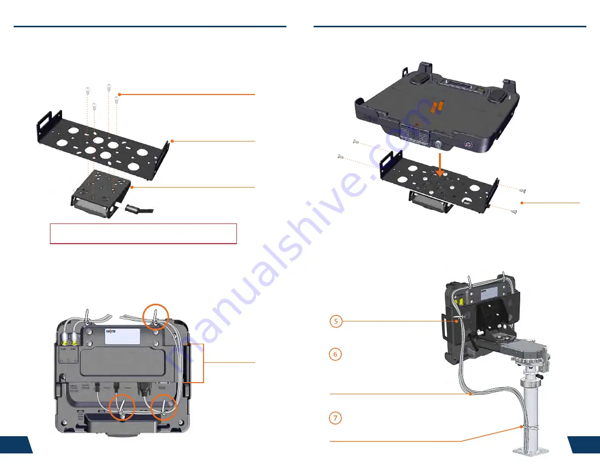
Cable Channel
1/4”-20 x 3/8” Screws
This loop must be large enough
to allow full range of expected
rotation and extension without
stressing connections.
Collect cables to secure
to the mounting system
(Note: mounting system not included)
1/4”-20 x 5/8” Screws
Typical Motion Device Example
(not included)
Mounting Bracket
6
7
Installation & Cable Management
(continued)
Installation & Cable Management
1)
Remove the Mounting Bracket from the packaging. Install the
Mounting Bracket to the Motion Device using (4) 1/4“-20 x 5/8” long
screws (Hardware Kit Item 3). Torque screws to 80 in-lbs (9.0Nm) ± 10%.
NOTE: Numerous hole patterns present in Mounting Bracket will accomodate Havis Motion
Devices as well as most competitors’
5)
Secure cable bundle to the Mounting Bracket with a supplied Zip Tie.
6)
Create a service loop with cable bundle to ensure that no tension is on the
connectors and to enable intended range of motion.
7)
Tie off cables onto a stationary part of the mounting system.
(Mounting system not included with Docking Station)
2)
Orient the Docking Station in a position that is comfortable to work with.
3)
Install all cables that are necessary for computing needs.
Use Zip Ties (Hardware Kit Item 1) to strain relieve cables to the Strain
Relief Points, routing all cables together through the Cable Channel and
out the rear of the Docking Station.
NOTE:
We recommend applying a drop of medium strength (blue)
thread locking adhesive to the threads of all fasteners.
4)
Lower the Docking Station to the Mounting Bracket as shown and secure
with (4) 1/4”-20 x 3/8” long screws (Hardware Kit Item 4). Ensure cable
bundle remains in Cable Channel before securing. Torque screws to
80 in-lbs (9.0 Nm) ± 10%.


