background image

13

ENGLISH

!

TABLE OF  CONTENTS 


z

Schematic Drawing ....................................................................................... p.10


z

Parts List ....................................................................................................... p.12


z

Important Safety Instructions ......................................................................... p.13


z

Unpacking ..................................................................................................... p.14


z

Operating Instructions ................................................................................... p.14


z

Preparing the tool .......................................................................................... p.15


z

Using the tool ................................................................................................ p.16


z

Fastener depth .............................................................................................. p.17


z

Maintenance .................................................................................................. p.17


z

Troubleshooting ............................................................................................. p.18


z

Warranty ........................................................................................................ p.19

IMPORTANT SAFETY INSTRUCTIONS

WARNING: 

When using pneumatic tools, basic safety precautions should 

always be followed to reduce the risk of personal injury.

READ ALL INSTRUCTIONS BEFORE USING THIS TOOL

We strongly recommend not to modify and/or use this tool for any application 

other than that for which it was designed. If you have any questions relative to its 

application, do not use the tool until you have contacted us.

1.  WEAR EYE PROTECTION. 

To prevent eye injuries, the tool operator and all 

persons in the work area must wear approved safety glasses to ANSI Z87.1 

specifications with permanently attached, rigid side shields.

2.  EAR PROTECTION

 Wear ear protection to prevent possible hearing loss.

3.  DRESS PROPERLY. 

Don’t wear loose clothing or jewelry; they can be caught 

in moving parts. Non-skid footwear are recommended when working. Wear 

protective hair covering to contain long hair and keep it from harm.

4.  USE CLEAN, DRY, REGULATED, COMPRESSED AIR

 at 70-120 PSI.

5.  DO NOT CONNECT TOOL

 to pressure which potentially exceeds 180 PSI.

6.  AIR HOSE

 Only use hose that is rated for a minimum working pressure of 150 

PSI or 150% of the maximum system pressure, whichever is greater. Check 

that connections are tight.

7.  NEVER USE OXYGEN, CARBON DIOXIDE,

 combustible gases or any other 

bottled gas as a power source for this tool. Explosion and serious personal 

injury could result.

8.  COUPLINGS

 Connect tool to air supply hose with a 1/4” NPT coupling that 

removes all pressure from the tool when the coupling is disconnnected.

9.  DISCONNECT TOOL FROM AIR SUPPLY HOSE

 before doing any 

disassembly, maintenance, clearing a jammmed fastener, leaving the work 

area, moving the tool to another location, or handing the tool to another person.

10. EXTENSION CORDS: 

Follow carefully the instructions that accompany 

air compressors concerning the use of the correct gauge and insulation on 

extension cords used outdoors.

11. NEVER USE A TOOL

 that is leaking air, has missing or damaged parts, or 

requires repair. Make sure all screws and caps are securely tightened.

12. CHECK FOR DAMAGED PARTS.

 Never use a tool if safety, trigger, or spring 

are inoperable, missing or damaged. Do not alter or remove safety, trigger, or 

springs. Make daily inspections for the free movement of trigger and safety 

mechanism.

13. REPLACEMENT PARTS. 

When servicing, use only identical replacement parts 

and fasteners recommended by the manufacturer.

14. CONNECT TOOL TO AIR SUPPLY BEFORE

 loading fasteners to prevent 

fasteners from firing during connection. The fastener driving mechanism may 

cycle when the tool is connected to the air supply.

Summary of Contents for HFN2890

Page 1: ...t parts ship from our facility in two business days For immediate help with assembly or for additional product information call our toll free number 1 866 599 5916 ext 2 C Notre personnel du Service à la Clientèle est disponible pour vous aider Dans le cas d une pièce endommagée ou manquante la plupart des pièces de remplacement seront expédiées de notre usine en deux jours ouvrables Pour de l aid...

Page 2: ... uniquement un tuyau d air calibré pour une pression de travail minimum de 150 lb po2 ou 150 du maximum du système de pression soit la plus élevée des deux mesures Assurez vous que les raccords sont bien serrés 7 N UTILISEZ JAMAIS D OXYGÈNE DE DIOXYDE DE CARBONE des gaz combustibles ou tout autre gaz embouteillé pour alimenter cet outil Une explosion pourrait se produire et causer des blessures 8 ...

Page 3: ...eculer de la surface de travail lorsqu un clou est éjecté 21 N ENFONCEZ PAS DE CLOUS sur d autres clous ou si l angle de l outil est trop prononcé les clous pourraient ricocher et causer des blessures 22 N ENFONCEZ PAS DE CLOUS trop près du bord de la pièce de travail La pièce de travail pourrait fendre et les clous seront projetés librement et pourraient causer des blessures 23 SOYEZ VIGILANT Mai...

Page 4: ...e vie de l outil Si un huileur n est pas présent placer 2 ou 3 gouttes d huile dans la prise d air de l outil au début de chaque jour de travail MISE EN GARDE z Toutes les composantes en ligne boyaux connecteurs filtres régulateurs etc doivent pouvoir soutenir 150 de la pression maximale du système Essayez d utiliser un boyau d un diamètre intérieur de 3 8 po 9 5 mm pour connecter la cloueuse au c...

Page 5: ...L avant d utiliser l outil Cet outil peut être utilisé de deux façons COUP PAR COUP SÉQUENTIELLE 1 Tournez le bouton de sélection de mode A fig 5 pour que la partie effilée soit vers le haut 2 Placez la pointe poussoir de contact C fig 6 sur la pièce 3 Appuyez légèrement sur la cloueuse pour enfoncer le dispositif de sécurité 4 Appuyez sur le déclencheur pour enfoncer les clous La méthode de décle...

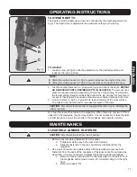
Page 6: ...age de profondeur est ajusté à la profondeur maximale à l usine RÉGLAGE 1 Desserrer la vis B fig 6 ajustez le réglage à la position désirée et resserrer la vis REMARQUES z z Remonter le dispositif de sécurité A fig 6 augmente la profondeur à laquelle le clou est enfoncé z z Abaisser le dispositif de sécurité A fig 6 diminue la profondeur à laquelle le clou est enfoncé 2 Faites l essai d un clou da...

Page 7: ...voir schéma à l avant gauche de l outil et les deux vis 35 à l avant droite b Retirez le support 73 c Glissez le chargeur pour le décrocher du nez de la cloueuse d Après avoir retiré le clou coincé réassemblez les pièces dans l ordre inverse ENTRETIEN RÉGULIER z z Nettoyer et inspecter l outil à tous les jours Assurez vous que la cloueuse est débranchée de l alimentation d air z z Nettoyez l outil...

Page 8: ...ndommagé Remplacez les composantes usées ou endommagées GARANTIE Merci d avoir acheté cet outil HAUSSMANN Ces outils ont été conçus pour répondre à des normes de haute qualité très strictes et sont garantis pour usage domestique contre tout défaut de fabrication pour 36 mois suivant la date d achat Cette garantie n affecte pas vos droits légaux En cas de mauvais fonctionnement de votre outil bris ...

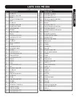
Page 9: ... M5 x 10 40 Coussinet en caoutchouc 41 Goupille à ressort 42 Plaque de guidage 43 Joint torique 20 3 x 2 5 44 Joint torique 20 3 x 1 5 NO DESCRIPTION 45 Ensemble de soupape 46 Joint torique 9 5 x 1 9 47 Joint torique 10 3 x 1 9 48 Tête de soupape du déclencheur 49 Joint torique 12 8 x 1 9 50 Ressort 51 Joint torique 5 5 x 1 5 52 Tige de soupape du déclencheur 53 Joint torique 24 8 x 2 54 Guide de ...

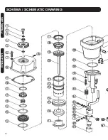
Page 10: ...10 FRANÇAIS ENGLISH SCHÉMA SCHEMATIC DRAWING ...

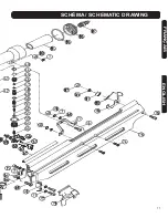
Page 11: ...11 FRANÇAIS ENGLISH SCHÉMA SCHEMATIC DRAWING ...

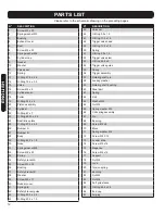
Page 12: ...Bushing 37 Safety bracket B 38 Washer 39 Screw M5 x 10 40 Rubber cover 41 Spring pin 42 Safety bracket guide 43 O Ring 20 3 x 2 5 44 O Ring 20 3 x 1 5 NO DESCRIPTION 45 Valve set 46 O Ring 9 5 x 1 9 47 O Ring 10 3 x 1 9 48 Trigger valve head 49 O Ring 12 8 x 1 9 50 Spring 51 O Ring 5 5 x 1 5 52 Trigger valve stem 53 O Ring 24 8 x 2 54 Trigger valve guide 55 Spring 56 Trigger assembly 57 Rotating s...

Page 13: ...6 AIR HOSE Only use hose that is rated for a minimum working pressure of 150 PSI or 150 of the maximum system pressure whichever is greater Check that connections are tight 7 NEVER USE OXYGEN CARBON DIOXIDE combustible gases or any other bottled gas as a power source for this tool Explosion and serious personal injury could result 8 COUPLINGS Connect tool to air supply hose with a 1 4 NPT coupling...

Page 14: ...uld be a problem 24 PREVENT ELECTRIC SHOCKS Prevent body contact with grounded surfaces pipes radiators ranges and refrigerator enclosures Before driving fasteners into walls floors or wherever live electrical wires may be encountered check whether there is a danger of shock 25 KEEP WORK AREA CLEAR of obstructions 26 STORE IDLE EQUIPMENT When the tool is not being used it should be cleaned and sto...

Page 15: ...is tool to a system with maximum potential pressure greater than 180 PSI z Disconnect your air line from your nailer using the quick connect on the air hose Do not unscrew the air inlet from the nailer with your air hose connected z Disconnect tool from air supply before performing maintenance clearing a jammed fastener leaving work area moving tool to another location or handing the tool to anoth...

Page 16: ... the trigger mode selector A fig 5 so the tail of selector is down 2 Hold the contact tip C fig 6 off the surface 3 Press the trigger 4 Keeping the trigger pressed push the contact tip of the safety bracket C fig 6 against the working surface Once the bracket is pushed back enough the nail will fire CAUTION z Remove your finger from the trigger when not driving fasteners z Never carry the tool wit...

Page 17: ...e marring of the work surface The cushion can be removed to increase the depth of the drive CAUTION Disconnect tool from the air supply before removing or installing the rubber cushion Don t use the tool without nails in the magazine When there are only two or three nails left in the magazine the tool may misfire It is not necessary to take the nails out Simply place a new strip of nails in the ma...

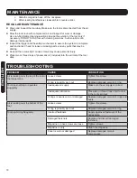
Page 18: ...nose screws are loose Tighten screws Magazine is dirty Clean the magazine Driver is worn or damaged Replace damaged or worn components TROUBLESHOOTING c Slide the magazine back off the nosepiece d After clearing bent fastener reassemble in reverse order REGULAR MAINTENANCE z z Clean and inspect the tool daily Make sure the tool is disconnected from the air supply z z Blow the tool clean with compr...

Page 19: ... line at 1 866 599 5916 Ext 2 from 8 AM to 6 PM Monday to Friday Eastern time RONA reserves the right to repair or replace the defective tool at its discretion Normal wear and tear including accessory wear is not covered under guarantee The product is guaranteed for 36 months if used for normal trade purposes Any guarantee is invalid if the product has been overloaded or subject to neglect imprope...

Reviews: