A
OPERATING INSTRUCTIONS
14
COMPONENT LIST
1. ON/OFF Trigger Switch
2. Cord Retainer
3. Motor Housing
4. Guard
5. Trimmer Head
6. Assist Handle
7. “Bump Feed” Mechanism
8. Spool Head Cover
9. Spool Head Cover Latch (on both sides)
10. Trimmer Head
11. Spool
12. Cutting Line
INCLUDED ACCESSORIES:
Guard
Wire Guard
Auxiliary Assist Handle
ASSEMBLY
Note:
Do not operate this trimmer until it is
assembled and installed according to the
instructions. A trimmer incorrectly assembled
can cause serious injury.
The guard must always be on the tool to
protect the user
Fig 2
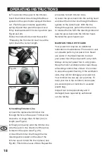
1) Shaft Assembly
Connect the upper and lower section of the
shaft by sliding the two sections together. The
two sections will be connected when a “click”
is heard. Ensure the screw holes located on
the sides of both sections of the shaft, line-up
on the same side (see Fig. 2).
Fig 3
screw
Fig 4
Fig 5


