background image

19

ENGLISH

SETUP & OPERATION

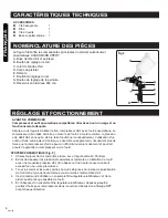
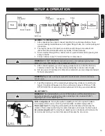
Fig.7

Air volume 

adjustment

Fluid 

adjustment

Pattern 

adjustment

ASSEMBLY & PREPARATION

1.    After unpacking the product, inspect carefully for any damage that may have 

occurred during transit. Make sure to tighten fittings, bolts, etc., before putting unit 

into service.

2.    Thoroughly mix and thin paint in accordance with the paint manufacturer’s 

instructions. Most materials will spray readily if thinned properly.

3.    Strain material through filter, cheese cloth or a paint strainer before pouring into 

spray container.

4.    Fill the container about ¾ full and start the air compressor.

5.    After connecting spray gun to air supply, please make sure that the fluid cap, 

container and air hose have been connected tightly to reduce risks of leaks.

6.    Set up a piece of cardboard or other scrap material to use as a target and adjust 

for best spray pattern.

7.    Test the consistency of the material by making a few strokes on a cardboard 

target. If material still appears too thick, add a small amount of thinner. THIN 

WITH CARE! Do not exceed paint manufacturer’s thinning recommendations.

ADJUSTMENTS
WARNING! 

The desired pattern, volume of fluid output, and fine atomization can 

easily be obtained by regulating the pattern adjusting knob, material (PAINT) 

adjusting knob and air adjusting knob.

Pattern adjustment:

 Turning the pattern adjusting knob to the right will make a 

round spray pattern round, or turning it left will make an elliptic spray pattern.

Fluid adjustment:

 Turning the paint adjusting knob clockwise will decrease the 

volume of fluid output and turning it counter-clockwise will increase the fluid output.

Air volume adjustment:

 Turning the air adjusting valve clockwise will decrease the 

air volume and turning it counter-clockwise will increase the air volume.

!

WARNING! 

DO NOT EXCEED maximum pressure of air-powered gravity-feed 

spray gun or any other parts in the compressor system.

!

!

WARNING! 

Never aim or spray at yourself or anybody else, which could cause 

serious injury.

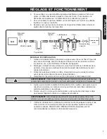
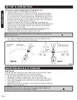
Fig.6

Quick

Connector

Tool

Quick Coupler

Air Hose

Quick

Coupler

Quick

Connector

Lubricator

Filter

Regulator

Cut-off

valve

Air

Compressor

Summary of Contents for 68125035

Page 1: ...r future reference QUESTIONS 1 866 206 0888 Notre personnel du service à la clientèle est disponible pour vous aider Pour obtenir de l aide pour le montage de votre produit pour signaler des pièces endommagées ou manquantes ou pour toute autre information veuillez composer notre numéro sans frais 1 866 206 0888 Enregistrez votre produit Nous vous invitons à enregistrer votre produit en ligne afin ...

Page 2: ...ute personne qui utilise cet outil CONSERVEZ CE MANUEL Gardez ce manuel qui contient les avertissements de sécurité les précautions à prendre le mode de fonctionnement les inspections et l entretien à effectuer Gardez ce manuel et le reçu dans un endroit sec et sécuritaire pour référence ultérieure SYMBOLES Certains des symboles suivants peuvent être utilisés sur cet outil Veuillez les étudier et ...

Page 3: ... de l utilisation de l outil Portez des vêtements appropriés Évitez de porter des vêtements amples ou des bijoux Attachez les cheveux longs Gardez les cheveux Ies vêtements et Ies gants à l écart des pièces mobiles Les vêtements amples bijoux ou cheveux longs pourraient se prendre dans les pièces mobiles Enlevez les clés de réglage avant de démarrer l outil Un outil ou une clé laissée sur une pièc...

Page 4: ...e Les accessoires adaptés à un outil peuvent devenir dangereux s ils sont utilisés sur un autre outil ENTRETIEN L outil ne doit être réparé que par un réparateur qualifié Pour réparer l outil n utilisez que des pièces de rechange identiques aux pièces originales Utilisez uniquement les pièces autorisées Utilisez uniquement le lubrifiant pour outils pneumatiques fourni et ou recommandé par le fabri...

Page 5: ...blessures graves voir la Fig 2 3 Les liquides et les solvants vaporisés peuvent être hautement inflammables et combustibles Veuillez utiliser l outil uniquement dans un endroit bien aéré et supprimez toutes les sources d allumage comme les cigarettes et les flammes nues voir la Fig 3 4 Déconnectez l outil du tuyau d alimentation d air avant d effectuer tout entretien de l outil et lorsque vous ne ...

Page 6: ...ales du pistolet pulvérisateur pneumatique HAUSSMANN XPERT A Buse de tête d air et pointeau B Bouton de réglage de l air C Joint de l entrée d air D Corps du pistolet E Détente F Boution de réglage du jet G Bouton de réglage de la peinture H Réservoir en plastique 600 cm3 SYSTÈME PNEUMATIQUE Fig 6 1 Utilisez toujours de l air comprimé propre sec et régulé entre 40 50 lb po2 2 Évitez de dépasser le...

Page 7: ...ure avant de les verser dans le réservoir de pulvérisation 4 Remplissez le réservoir environ aux 3 4 et démarrez le compresseur d air 5 Après avoir connecté le pistolet à l alimentation d air veuillez vous assurer que le capuchon à peinture le contenant et le tuyau d air sont raccordés solidement au pistolet pulvérisateur pneumatique 6 Servez vous d un morceau de carton solide ou de tout autre reb...

Page 8: ...ance égale de la surface à peinturer Arrêter le mouvement du pulvérisateur au milieu du déplacement forme une accumulation de peinture et entraîne des coulées N agitez pas le pistolet de gauche à droite lorsque vous peinturez ce qui pourrait entraîner une accumulation de peinture au centre et un revêtement insuffisant de chaque côté 3 Commande de la détente Commencez toujours à déplacer le pistole...

Page 9: ...ttoyez tous les autres composants en utilisant une brosse trempée dans le solvant 4 Remontez le pistolet pulvérisateur et pulvérisez une petite quantité de solvant pour éliminer tous les résidus dans les passages de peinture ENTREPOSAGE Lorsque vous n utilisez pas le pistolet pulvérisateur pneumatique tournez le bouton de réglage du liquide dans le sens antihoraire pour l ouvrir ce qui réduira la ...

Page 10: ...z ouvert 3 Le liquide est trop épais 1 Vérifiez les conduites d air 2 Ouvrez le réglage du liquide 3 Diluez le liquide ou changez la pression du système d alimentation Le pistolet de pulvérise pas Merci d avoir acheté cet outil HAUSSMANN XPERT Ces outils ont été conçus pour répondre à des normes de haute qualité très strictes et sont garantis pour usage domestique contre tout défaut de fabrication...

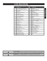
Page 11: ... de détente II Détente Frein pression Rondelle de détente Tête de ventilateur Couvercle du godet Godet Filtre Joint d arrivée de peinture Pointeau de réglage de la peinture Ressort du pointeau Joint Bouton de réglage de la peinture Boulon Vis de réglage du jet Bouton de réglage du jet Rondelle de cuivre Vis de réglage du jet Joint torique Corps de pistolet Joint de l entrée d air Clé hexagonale Cl...

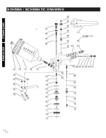
Page 12: ...FRANÇAIS PNT152 12 ENGLISH SCHÉMA SCHEMATIC DRAWING ...

Page 13: ...er pin I Trigger pin II Trigger Snap retainer Trigger washer Ventilator head Cup cover Cup Filter Fluid inlet joint Fluid Adj needle Fluid needle spring Joint Fluid Adj Knob Bolt Pattern Adj Screw Pattern Adj knob Copper washer Pattern Adj screw O ring Gun body Air inlet joint Hex wrench Tool wrench 27 28 29 30 31 32 33 34 35 36 37 38 39 40 41 42 43 44 45 46 47 48 49 50 51 Please refer to the Sche...

Page 14: ...ith side shields or a full face shield when operating this product Risk to hearing Always wear ear protection when using this tool Failure to do so may result in hearing loss WARNING The warnings and precautions discussed in the manual cannot cover all possible conditions and situations that may occur It must be understood by the user that common sense and caution are factors which cannot be built...

Page 15: ...nal injuries Do not overreach Keep proper footing and balance at all times Proper footing and balance enables better control of the tool in unexpected situations Use safety equipment A dust mask non skid safety shoes and a hard hat must be used for applicable conditions Always wear eye protection Always wear hearing protection when using the tool Extended exposure to high intensity noise may cause...

Page 16: ...zed parts Use only the lubricants supplied with the tool and specified by the manufacturer AIR SUPPLY AND CONNECTIONS The air supply connection must not hold pressure when air supply is disconnected If an incorrect fitting is used the tool can remain charged with air after disconnecting and thus will be able to work even after the air line is disconnected possibly causing injury Do not use any typ...

Page 17: ...ts can be highly flammable or combustible Please use the tool in a well ventilated area only and avoid any ignition sources such as smoking or open flames see Fig 3 4 Disconnect tool from air supply hose before doing tool maintenance and during non operation For emergency stops and prevention of unintended operation a ball valve near the gun to air supply is recommended 5 Use clean dry and regulat...

Page 18: ... rapid wear 3 Keep hands and other parts of the body away from the tool s discharge and working areas when connecting the air supply 4 It is recommended that a filter regulator lubricator be used and that it be located as close to the tool as possible 5 If a filter regulator lubricator is not installed place up to 6 drops of compressor oil into the NPT inlet plug before each use 6 If a filter regu...

Page 19: ...till appears too thick add a small amount of thinner THIN WITH CARE Do not exceed paint manufacturer s thinning recommendations ADJUSTMENTS WARNING The desired pattern volume of fluid output and fine atomization can easily be obtained by regulating the pattern adjusting knob material PAINT adjusting knob and air adjusting knob Pattern adjustment Turning the pattern adjusting knob to the right will...

Page 20: ...at 6 Use a piece of cardboard as a shield to capture the loss of spray paint to the ends of the piece to paint to protect the other surfaces NOTE Two thin coats of paint will yield better results and have less chance of runs than one heavy layer WARNING Never use metal or other objects that could damage the holes in the nozzle and cap Never immerse the spray gun completely in solvent Never use com...

Page 21: ...p on air cap 1 Add fluid into container 2 Hold more upright 3 Tighten 4 Adjust or replace 5 Lubricate and or tighten 6 Clear vent hole 1 Tighten or replace fluid nozzle 2 Remove obstructions from holes but don t use metal objects to clean it 1 Material build up on air cap 2 Fluid nozzle is dirty or worn 1 Clean or replace air cap 2 Clean or replace fluid nozzle The centre of pattern too narrow Pat...

Page 22: ...se This guarantee does not affect your statutory rights In case of any malfunction of your tool failure missing part etc please contact one of our service technicians at our toll free service line at 1 866 206 0888 from 8 AM to 6 PM Monday to Friday Eastern time RONA reserves the right to repair or replace the defective tool at its discretion The product is guaranteed for 36 months if used for nor...

Reviews: