background image

Page 6

For technical questions, please call 1-800-444-3353.

Item 60708 


Installation Instructions

  Read the ENTIRE IMPORTANT SAFETY INFORMATION section at the beginning of this 

manual including all text under subheadings therein before set up or use of this product.

Note:

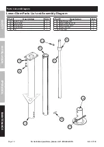
  For additional information regarding the parts listed in the following pages, refer to 

Parts List and Assembly 

Diagram 

on page 10. 

Mounting

This Electric Jack is designed to replace an existing 

manual-only trailer jack.  Check that the Outer 

Tube (1A) of the Electric Jack will fit into the existing 

jack location and that the Mounting Plate holes align 

with the bolt locations on your trailer.  Only a qualified 

technician should modify the trailer if needed.

1.  Block the wheels and support the trailer A-Frame 

securely using jack stands (sold separately).

2.  Disconnect the trailer battery 

ground cable, if equipped.

3.  Remove the existing jack. 

4.  Remove the Lock Pin (9A) and slide out 

the Footpad (10A) from the Jack.

5.  To ensure proper grounding, remove paint from 

around one bolt hole on the Jack, and remove 

paint from around the matching bolt hole on the 

trailer tongue.  If the paint layer is thick, add a flat 

washer (sold separately) between the jack and the 

trailer to provide good contact.  Exposed metal can 

be painted after assembly to inhibit corrosion.

6.  Insert the bottom section of the Outer Tube (1A) into 

the A-Frame jack opening so that the Motor Housing 

is toward the front of the trailer and the Mounting 

Plate holes line up with the bolt holes in the trailer.

Align bolt holes

Rotate 

so Motor 

faces 

forward

Insert Jack into trailer opening

7.  Secure the Mounting Plate to the A-Frame using 

nuts, bolts and washers (all sold separately) as 

listed under Hardware in the Specifications chart 

on page 4.  Slide a star washer onto each bolt, 

then insert them from the top side and attach a star 

washer and lock nut from the underside of the frame.  

Tighten mounting hardware firmly to 15 – 20 ft. lb.  

Use a torque wrench to confirm tightness.

8.  Replace the Footpad and insert the Lock Pin.

Wiring

The Jack needs to be properly wired for use.  Have 

a qualified technician perform the wiring if you 

are not familiar with the following procedures.

1.  If wiring to the trailer’s electrical system, 

disconnect the trailer battery ground cable.  

Connect the black wire lead from the Jack to 

the positive (+) battery terminal and include 

an ON/OFF switch and fuse (sold separately) 

in the wiring so you can turn off power to the 

unit.  Reconnect the battery ground cable.

Note:

  If connecting to the trailer’s electrical 

system, do not exceed its rating.

2.  If wiring to the vehicle battery, route a 10-gauge wire 

(sold separately) from the positive (+) terminal of a 

12VDC battery to a location near the Jack.  Attach the 

female side of a quick connect (sold separately) to 

the end of the wire and the male side to the positive 

Jack wire.  Plug the quick connect sections together. 

SAFETY

OPERA

TION

MAINTENANCE

INST

ALLA

TION

Summary of Contents for 60708

Page 1: ......

Page 2: ...AFETY INFORMATION Read all safety warnings and instructions Failure to follow the warnings and instructions may result in serious injury Save all warnings and instructions for future reference Basic Safety Information Keep work area clean and well lit Cluttered or dark areas invite accidents Personal safety 1 Stay alert watch what you are doing and use common sense when operating a tool Do not use...

Page 3: ... ground clearance 13 Do not climb aboard any vehicle supported by jack 14 This product is not a toy Keep it out of reach of children 15 Follow all state regulations for towing when using Trailer Jack including using safety chains securely attached to the towing vehicle when the trailer is hooked to the vehicle 16 Check ground clearance carefully after installing If your trailer does not provide en...

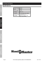
Page 4: ...l Description Specifications Weight Capacity 3 500 lb Motor 12VDC Travel Length 19 5 8 Lift Range 8 3 8 28 Application For use with A frame trailers Hardware sold separately 3 bolts 3 8 D x 1 L grade 5 or better 3 lock nuts 6 star washers SAFETY OPERATION MAINTENANCE INSTALLATION ...

Page 5: ...Page 5 For technical questions please call 1 800 444 3353 Item 60708 Components Light Switch Crank Light Power Switch Mounting Plate Outer Tube Footpad Lock Pin SAFETY OPERATION MAINTENANCE INSTALLATION ...

Page 6: ...the A Frame jack opening so that the Motor Housing is toward the front of the trailer and the Mounting Plate holes line up with the bolt holes in the trailer Align bolt holes Rotate so Motor faces forward Insert Jack into trailer opening 7 Secure the Mounting Plate to the A Frame using nuts bolts and washers all sold separately as listed under Hardware in the Specifications chart on page 4 Slide a...

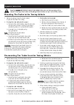
Page 7: ...y engaged continue to retract Jack up to the STOP label on the Inner Tube 2A Trailer Jack must always be fully retracted when towing the trailer 8 Attach the safety chain sold separately Dismounting The Trailer from the Towing Vehicle 1 Before dismounting chock the trailer wheels to prevent the trailer from rolling 2 If using the Jack with electric power a If wired to the vehicle battery plug the ...

Page 8: ... FAILURE Do not use damaged equipment If abnormal noise or vibration occurs have the problem corrected before further use Cleaning Maintenance and Lubrication 1 BEFORE EACH USE inspect the general condition of the tool Check for loose hardware misalignment or binding of moving parts cracked or broken parts any other condition that may affect its safe operation 2 AFTER USE wipe external surfaces of...

Page 9: ...UCT IN FACT THE MANUFACTURER AND OR DISTRIBUTOR EXPRESSLY STATES THAT ALL REPAIRS AND PARTS REPLACEMENTS SHOULD BE UNDERTAKEN BY CERTIFIED AND LICENSED TECHNICIANS AND NOT BY THE BUYER THE BUYER ASSUMES ALL RISK AND LIABILITY ARISING OUT OF HIS OR HER REPAIRS TO THE ORIGINAL PRODUCT OR REPLACEMENT PARTS THERETO OR ARISING OUT OF HIS OR HER INSTALLATION OF REPLACEMENT PARTS THERETO Record Product s...

Page 10: ...ts List and Assembly Diagram Part Description Qty 1A Outer Tube 1 2A Inner Tube 1 3A Bronze Nut 1 4A Jack Screw 1 5A Pin 1 Part Description Qty 6A Set Screw 3 8 1 7A Lock Washer 5 16 4 8A Cap Screw 5 16 4 9A Lock Pin 3 8 1 10A Footpad 1 3A 6A 4A 8A 9A 7A 2A 1A 5A 10A SAFETY OPERATION MAINTENANCE INSTALLATION ...

Page 11: ... Main Gear 1 9 Light 2 10 Housing Cover 1 11 Drive Collar 1 12 Washer 2 13 Thrust Bearing 1 14 Pin 1 15 Pin 1 Part Description Qty 16 Lock Washer 1 4 1 17 Cap Bolt 1 4 1 18 Screw 8 32 8 19 Motor Housing 1 20 Power Switch Housing 1 21 Screw 5 40 4 22 Motor 1 23 Power Switch 1 24 Level Gauge 1 25 Grommet 1 26 Power Switch Cover 1 27 Circuit Breaker 1 28 Screw 2 29 Light Switch 1 30 Crank 1 SAFETY OP...

Page 12: ... the exclusion or limitation of incidental or consequential damages so the above limitation of exclusion may not apply to you THIS WARRANTY IS EXPRESSLY IN LIEU OF ALL OTHER WARRANTIES EXPRESS OR IMPLIED INCLUDING THE WARRANTIES OF MERCHANTABILITY AND FITNESS To take advantage of this warranty the product or part must be returned to us with transportation charges prepaid Proof of purchase date and...

Reviews: