HATRIA thank you for choosing the
FUSION BATT
electronic system for urinal pod. To obtain the optimum performance,
please read and follow carefully the instructions contained in this leaflet.
INSTALLATION AND MAINTENANCE INSTRUCTIONS
1
IMPORTANT - BEFORE INSTALLING THE ELECTRONIC SYSTEM FUSION BATT
m
in
.
1
8
0
c
m
Before installing the electronic flushing system
FUSION BATT
,
verify that the entrance door to toilet or the front wall (FIG. 6) do
not interfere with the sensors beam which is set to 30 cm.
Therefore, it is recommended to install the
FUSION BATT
in locals
having the measurements shown in FIG. 6.
FIG. 6
ATTENTION - BEFORE INSTALLING
OPERATION AND NOTE FOR ADJUSTING THE SENSORS BEAM
3
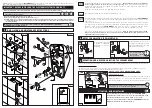
Fix the drilling diagram to the wall in order to centre the holes.
Ensure that the centre of the drainage
hole is at approx. 40,5 cm from the floor according to fig. 9.
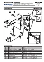
Fix to the wall the upper plate (1)
through the parts (18) and the supplied 3 nogs and 3 screws (2). Then mount the lower plate (17)
using 2 nogs and 2 screws (2).
Screw the shut-off tap (3) to the ½ G plumbing outlet on the wall.
The installation should be according to the drawing Fig. 1/B
Insert the drainage siphon (4) in the wall; ensure that the pipe is perfectly watertight. Hook
FUSION BATT
to the lower plate (17) and carefully connect the siphon black rubber ring (4); hook the chain (5) to the
upper plate (1).
Connect the flexible hose (8) to the shut-off valve (3) then open the water flow on the shutt-off tap (3)
(see Fig. 3 an Fig. 4). Fasten the connectors (16) between the battery pack (22) and the electronic circuit
through a screw driver. Close
FUSION BATT
and screw the screws (7) together with the plastic
spacers (15). Be careful not to break the screws. Cover the screws with the supplied covers (14).
The circuit is activated when the user is in front of the sensor;
when he has been detected a red LED
(LR) is on in the circuit (fig. 2). Once the user has left, the flush will start and continues for an
adjustable time (see par. 3 fig. 5).
The circuit will activate an automatic flush each 12 hours
for approx. 30 sec. after the last operation.
!
!
• Water feed pipes must be of minimum 1/2 G and a min. water flow of 15/20 litres per minute at 3 bar.
1) Before connecting the water supply ensure that the pipework is blown clean of any debris which
could damage the electrovalves
2) The water temperature must not exceed 60°C.
3) The pressure supply range must be between
0.4 ÷ 7 bar.
4) In hard water areas, i. e. water producing limescale deposits, an appropriate water softener or purifier must be fitted to
avoid harmful deposits in the electrovalves. Please note that any failures due to debris or limescale deposits will not be
covered by warranty.
IMPORTANT: FOR THE INSTALLATION FOLLOW CAREFULLY (WATER DRAINAGE CONNECTION)
THE DIMENSIONS SHOWN AT FIG. 9.
!
15
14
1
7
15
14
8
16
22
G1/2
G1/2
ø 40
IN
OUT
17
3
4
6
5
7
LR
FIG. 2
2
3
2
2
18
1
17
FIG. 1/C
FIG. 1/A
FIG. 1/B
1st STEP
Fig.1/A
3
rd
STEP
Fig.1/C
2
nd
STEP
Fig.1/B
It is possible to adjust the sensor beam (max 70 cm) by turning the POTENTIOMETER(12). The sensor beam is pre-set at 30 cm.
CHANGE OF PRE–SET BEAM:
1
- Take the screw covers (14) out, unscrew the screws (7) and plastic spacers (15) with the screwdriver (see fig. 1/C)
2
- Unhook and carefully incline the urinal pod towards the floor (see fig. 9).
12
REGOLAZIONE
RAGGIO
D’AZIONE
REGOLAZIONE
TEMPO
13
CIRCUIT “SB39”: FLUSH WHEN MOVING AWAY:
TIME AND WATER FLOW:
When the user is in front of the sensors water does not flow. The flush
starts after approx 2 sec. the user has left. The water flow time is
adjustable from approx. 2 to 12 sec. by turning the potentiometer (13).
FIG. 5
SB39
A) Through the lever (9) it
is possible to adjust the
water flow or to stop it
completely.
NOTES FOR ADJUSTING THE WATER FLOW
2
9
Chiuso
Aperto
3
10
11
3
A
B
FIG. 3
OPEN
CLOSED
FIG. 4
B) By unscrewing the cap (11) it is
possible to clean the filter (10) from
deposits and impurities that could
damage the electrovalves.
It is recommended to
periodically
effect
this operation.
!
!
SENSORS BEAM
SETTING
TIME SETTING
!
!


