2. Center punch and drill a 3/4" (19 mm) pilot hole at each of
the two center marks on the template.
NOTE: The pilot holes are for cutting larger holes with a
knockout hole punch.
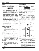
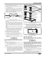
3. Remove the template and cut a 2" (51 mm) diameter hole
at each pilot hole location using a knockout hole punch.
4. Make a 1/8" (3 mm) offset around each 2" (51 mm)
diameter hole. The offset should be a diameter of 3"
(76 mm) centered around the hole.
Side View of Hole and Offset
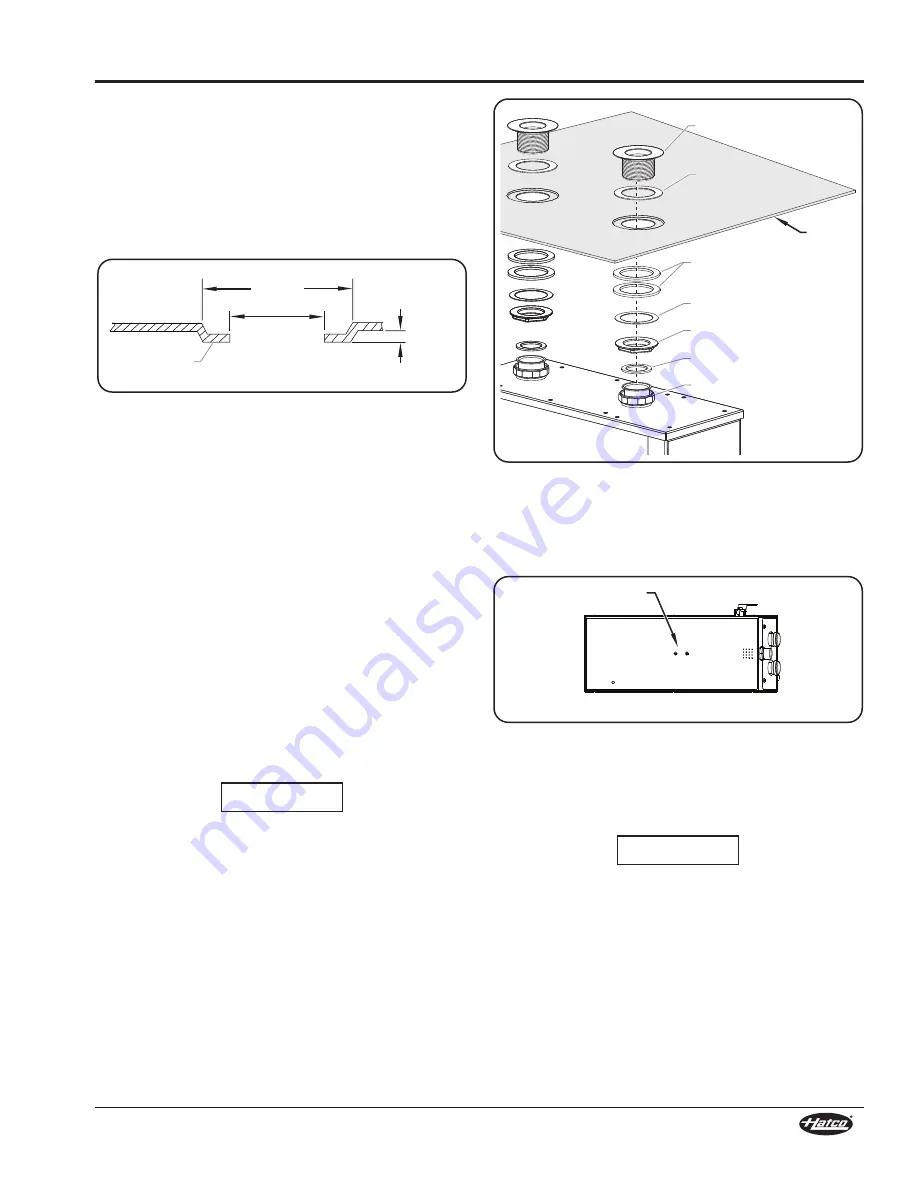
5. Unscrew the drain spud assembly from the welded pipe on
the heater.
6. Unscrew the locknut from the drain spud assembly and
slide off all of the washers except the thin rubber washer.
7. With only the thin rubber washer attached to the drain
spud, slide the drain spud through the sink hole from
above.
8. Secure the drain spud assembly to the sink or holding
vessel.
a. From under the sink, slide the two thick rubber washers
followed by the fiber washer onto the drain spud.
b. Screw the locknut (flat side up) onto the drain spud.
9. Repeat steps 5–8 for the other spud assembly.
10. Secure the unit to the sink or holding vessel.
a. Position the unit under the two spud assemblies.
NOTE: Make sure the union washers are positioned properly
inside the union nuts and are not crimped.
b. Screw the union nut to the threaded drain spud
assembly.
Do not use excessive force when tightening unions or
nuts. Over-tightening and excessive force may cause
leaks.
11. Tighten all of the nuts securely.
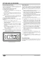
NOTE: Refer to the
OPTIONS AND ACCESSORIES
section for
Auto-Fill installation information.
12. Fill the sink or holding vessel with water and check for
leaks.
NOTE: A 3/4" (19 mm) hose or pipe may be connected to the
heater drain and run to an open sight drain. The heater
drain should not be permanently connected to the
sanitary drain system. The clean-out brush must have
access to the heater drain(s). Check local plumbing
code for proper drain installation. See the Maintenance
section for more information.
2”
(51 mm)
Dia. Hole
3”
(76 mm)
Dia. Offset
1/8”
(3 mm)
Offset
Height
Sink or Tank
Bottom
NOTICE
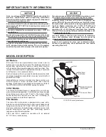
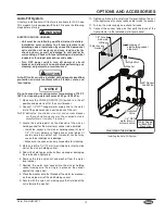
Installing a Hydro-Heater
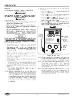
NOTE: Units exposed to movement, such as shipboard
installations, must be stabilized before operating. Two
anti-sway anchor points are located on the bottom-
center of the unit. Attach stabilization hardware to these
points using the 1/4" screws supplied.
Anti-Sway Anchor Points
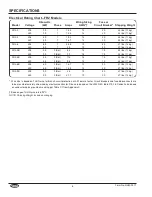
Electrical Information
Hatco 3CS2 and FR2 Series Hydro-Heaters are available for
operation with standard power systems. Check the specification
label for the proper power supply.
Units are voltage-specific. Refer to specification label for
electrical requirements before beginning installation.
Connecting unit to incorrect power supply will void product
warranty and may damage unit.
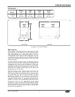
Units come complete with all electrical wiring and are equipped
with three electrical knockouts, one at the rear and one on each
side toward the rear. When performing installation, run electrical
connections through one of these knockouts.
NOTE: Auto-Fill models are provided with two electrical
knockouts, one at the rear and one on the right-hand
side toward the rear.
Only specific models FR2-3 and FR2-4 Hydro-Heaters can be
ordered and supplied with an electrical cord and plug.
Thin Rubber
Washer
Thin Rubber
Washer
Drain Spud
Sink/
Vessel
Bottom
Two Thick
Rubber Washers
Fiber Washer
Locknut
Union Washer
Union Nut
NOTICE
Bottom View
Anti-Sway Anchor
Point Screws
9
Form No. HHM-0517
INSTALLATION