
APEX
™
Exciter Incorporating FLO
™
Technology
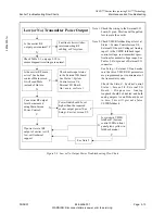
Typical Settings for the More Critical Exciter Setups
Maintenance and Troubleshooting
26
04s50
0.fm
03/08/07
888-2604-001
Page: 5-11
WARNING: Disconnect primary power prior to servicing.
5.4
Typical Settings for the More Critical Exciter Setups
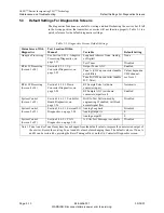
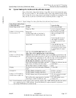
Some of the critical setups, which can have a large effect on exciter and transmitter opera-
tion, are given in Table 5-2. The remainder of the exciter setups should be fairly obvious
when viewing the various setup screens. For additional information concerning the exciter
setup screens, see Section 3.6, Details of the System Setup Screens, on page 3-32.
Table 5-2 Typical Settings For Some of the More Critical Exciter Setup Functions
Setup Screen and location in
Technical Manual
Function
Typical Setting
Exciter Setup (screen 1 of 2)
Section 3.6.2, Exciter Setup
Screen, on page 3-35
Channel
Set to correct channel
Frequency Offset
Set to 0 or required offset in
Hz, the limit is +/- 50 kHz.
Waveguide
Provides group delay precorrection to
compensate for waveguide group delay.
None, if waveguide group
delay precorrection is not
required.
Select waveguide type and
enter length if waveguide
group delay precorrection is
required.
Power Limit
Limits maximum exciter
power output (or transmitter
power output, if exciter is used
to control transmitter output
power)
RTAC Setup
Section 3.6.3, RTAC Setup
Screen, on page 3-38
Filter Type:
Use FLO BANDPASS
for this exciter.
Other Apex exciter application may use the following.
Standard
if the standard D-Mask filter is used.
Use Asymm
(asymmetrical) if the
sharp tuned filter (sometimes called “Cool Fuel”) is used or if the group delay for
the transmitter is not symmetrical, such as when its output is reflected through an
adjacent channel sharp tuned filter in order to combine the two transmitters.
Exciter must be restarted
to make filter change active.
Max. Peak Stretch (prevents nonlin correction
peaks form over driving solid state amps).
3db (may be set lower on some
transmitters.)
Off Air Mode (choices are Hold or Bypass)
Hold
Display
Chart Source (exciter spectrum analyzer display
input)
Tx Post HPF
External I/O
Section 3.6.5, External I/O
Setup Screen, on page 3-42
VSWR Foldback Threshold (low limit)
0.25 Vdc, see Note 1
VSWR Foldback Threshold (high limit)
5.0 Vdc, see Note 1
VSWR Foldback (max RF power reduction)
50% of normal exciter output
power, see Note 1
RF Cutoff (exciter output power level at which
control logic switches to backup exciter)
50% of the normal exciter
output power.
Note 1. Some transmitters use this feature for the transmitter output system VSWR foldback and other transmitters
use a separate circuit for VSWR foldback. Consult the transmitter technical manual for instructions
concerning VSWR foldback system and setup.


