background image

9

4.0 Operation

4.3 Hoist 

Controls

4.3.1 

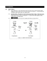
Single Speed Hoists – Firmly hold the black Grip on the cylinder control.  Slide the Up/Down Switch
Operator up to raise the load or down to lower the load as shown in Figure 4-1.  To stop the hoist slide
the Up/Down Switch Operator back to the middle position.

4.3.2 

Dual Speed Hoists – Select high or low speed using the Speed Selector Switch.  Lights ajacecnt to the
Speed Selector Switch indicate if low or high speed is selected. Slide the Up/Down Switch Operator up
to raise the load or down to lower the load Figure 4-1.  To stop the hoist slide the Up/Down Switch
Operator back to the middle position.

4.3.3 

CAUTION

Make sure the motor completely stops before reversing direction.

Single Speed

Dual Speed

Figure 4-1  Cylinder Control Operation

Summary of Contents for ER Series

Page 1: ...t and Serial Number WARNING This equipment should not be installed operated or maintained by any person who has not read and understood all the contents of this manual Failure to read and comply with...

Page 2: ...5 Ton Capacity will be designated by the use of the acronym EROM Table of Contents Section Page Number 1 0 Important Information and Warnings EROM 1 1 Terms and Summary EROM 1 2 Warning Tags and Label...

Page 3: ...thods and Criteria EROM 6 0 Maintenance Handling EROM 6 1 Count Hour Meter EROM 6 2 Lubrication EROM 6 3 Motor Brake EROM 6 4 Load Chain EROM 6 5 Friction Clutch and Mechanical Load Brake with Frictio...

Page 4: ...lectronic count hour meter in the control circuit Refer to Figure 2 1 for the visual differences between the ER and NER Figure 2 1 Identifying ER verses NER Models 2 1 3 Operating Conditions and Envir...

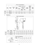
Page 5: ...1 79 Dual Speed 1 4 ER003SDCC 6 29 10 0 6 0 2 2 9 2 4 1 5 1 2 5 5 0 X 1 79 2 2 Dimensions Table 2 2 Hoist Dimensions Cap Tons Product Code Headroom C D in a in b in d in e in f in g in h in i in 1 8 E...

Page 6: ...re 3 1 Chain Component Location 3 2 2 Chain Container Install the chain container on the hoist body as shown in Figure 3 2 To place the chain into the chain container feed the chain into the chain con...

Page 7: ...ension point 3 4 4 CAUTION Mount the hoist at a height that will allow the operator to maintain a clearance of at least 4 inches between the Cushion Rubber and the hoist body during operation 3 4 5 WA...

Page 8: ...outside the hoist s Cable Support as shown in Figure 3 3 Use the Cable Trolleys supplied with the hoist to suspend the Power Supply Cable from the guide wire Space the Cable Trolleys every 5 feet Figu...

Page 9: ...osition 4 3 2 Dual Speed Hoists Select high or low speed using the Speed Selector Switch Lights ajacecnt to the Speed Selector Switch indicate if low or high speed is selected Slide the Up Down Switch...

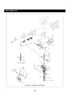
Page 10: ...10 10 0 Parts List Figure 10 1 Cylinder Control Parts...

Page 11: ...witch Set D 1 C20013H1020 11 Truss Head Screw 1 TRUSSM4X10 5P Plug S 1 ES613003 12 8P Plug D 1 ESM538010 13 Warning Tag 1 WTAG7 14 Cable Holder A 1 CD1BS9750 15 Cable Holder B 1 CD1BS9751 16 Cable Tie...

Page 12: ...rrington Hoists Western Division 401 West End Avenue 2341 Pomona Rincon Rd 103 Manheim PA 17545 1703 Corona CA 92880 6973 Phone 717 665 2000 Phone 909 279 7100 Toll Free 800 233 3010 Toll Free 800 317...

Reviews: