7-6 Details of tune mode
7-13
1
2
3
4
5
6
7
8
9
10
11
Appe
Stat
us di
spl
ay m
ode/
al
ar
m
m
ode/
tune m
ode
7-6
Details of tune mode
The following explains the details of settings in the tune mode.
AJ00: Position loop gain
Adjust the proportional gain of the position feedback loop.
The relation between the set value and actuator operation is as follows:
Increasing the set value: The position deviation decreases and following accuracy relative to the
command increases, but setting too high a value makes the servo
system unstable and prone to vibration (hunting).
Decreasing the set value: Setting too low a value results in poor following accuracy relative to the
command.
Set the highest gain within the limits of no vibration (hunting) and minimum overshoot.
Perform a trial operation with a higher servo gain to shorten the positioning period. If the value of [d04:
Overload rate display] remains 0 in the status display mode after the actual operation, the higher servo
gain can be used.
Set value
Function
Unit
Default
10 to 9999
Set the proportional gain of the
position feedback loop.
-
*
Relational items
AJ01, AJ02, AJ03, d04
*: The default varies depending on the applicable actuator. Refer to [Default settings] (PA-1) in the appendix.
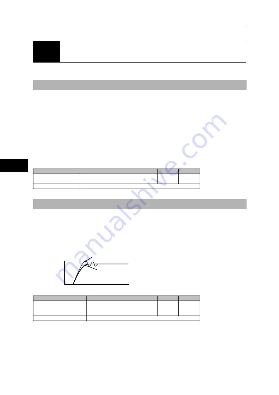
AJ01: Speed loop gain
Adjust the proportional gain of the speed feedback loop.
The relation between the set value and actuator operation is as follows:
Increasing the set value: Servo rigidity increases along with response, but setting too high a value
makes the servo system unstable and prone to vibration (hunting) and
overshoot.
Decreasing the set value: Setting too low a value leads to poor response and following accuracy.
Set value
Function
Unit
Default
HA-800-1: 0.1 to 999.9
Except HA-800-1: 1 to
9999
Set the proportional gain of the
speed feedback loop.
-
*
Relational items
AJ00, AJ02, AJ03
*: The default varies depending on the applicable actuator. Refer to [Default settings] (PA-1) in the appendix.
Overshoot
Best
Speed
Time
Summary of Contents for H A - 800A
Page 60: ...2 6 Wiring the host device 2 21 4 2 2 1 9 8 7 6 9 8 Installation wiring...
Page 86: ...3 6 Normal operation 3 25 4 3 3 1 9 8 7 6 9 8 Startup...
Page 152: ...5 8 Connection example in control mode 5 35 1 2 3 4 5 6 7 8 9 10 11 Appe I O signals...
Page 166: ...6 1 Operating display panel 6 13 11 10 9 4 7 6 5 4 3 2 1 Panel display and operation...
Page 206: ...8 2 Function extension parameter 8 17 1 2 3 4 5 6 7 8 9 10 11 Appe System parameter mode...
Page 222: ...9 2 Details of test mode 9 15 1 2 3 4 5 6 7 8 9 Test mode...
Page 270: ...11 2 Warnings and remedial actions 11 17 1 2 3 4 5 6 7 8 9 10 11 Appe Troubleshooting...
Page 271: ...1 16 Chapter 12 Option Options you can purchase as necessary are explained 12 1 Option 12 1...
Page 276: ...12 1 Option 12 5 1 2 3 4 5 6 7 8 12 Option...


