background image


User Interface Options

3–4

Copyright © 2005 Harmonic Inc.


3.1.3

Receiver A, B, C, D Menus


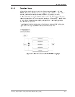
The Receiver A, B, C, and D menus allow you to obtain diagnostic 
information and make adjustments to a specific receiver (A, B, C, or D) 
of the HRR 4104. The Receiver A menu is shown in Figure 3-3.


Figure 3-3. Receiver A menu (HLP 4200WD display)

Summary of Contents for HRR 4104

Page 1: ...HRR 4104 Return Path Receiver Product Manual Manual Part No 700 0051981 Rev A March 2005...

Page 2: ...oduct designs Specifications are subject to change without notice Harmonic and logo design eXchange MAXLink METROLink NETWatch PWRBlazer TRANsend and Redefining the Network are trademarks of Harmonic...

Page 3: ...gnal Output 2 8 Chapter 3 User Interface Options 3 1 HLP 4200WD Display 3 1 3 1 1 Main Menu 3 1 3 1 2 Receiver Menu 3 3 3 1 3 Receiver A B C D Menus 3 4 3 1 4 Module Menu 3 6 3 2 NETWatch Site Control...

Page 4: ...1 1 Cleaning Patch Cord or Pigtail Fiber Optical Connectors 5 2 5 1 2 Cleaning HRR 4104 Optical Connectors 5 2 5 2 Troubleshooting 5 2 5 3 In Case of Problems 5 4 5 4 Disclaimer 5 4 5 5 Warranty Summa...

Page 5: ...round the world 1 2 Description The HRR 4104 is a high performance optical return path receiver that is optimized to operate in the 5 to 100 MHz return band This compact half slot plug in module is de...

Page 6: ...P 4200 Figure 1 2 shows front and rear panel features of the HRR 4104 Figure 1 1 HRR 4104 block diagram Figure 1 2 HRR 4104 front and rear panel features Factory use only Status LED Select LED RF Moni...

Page 7: ...with the platform controller via the platform communication bus For additional information on the HLP 4200 Platform and its associated communication and power buses see the HLP 4200 Platform Product M...

Page 8: ...Overview 1 4 Copyright 2005 Harmonic Inc...

Page 9: ...the input fiber cables How to test RF signal output 2 1 Receiving and Inspecting As you unpack your unit inspect the shipping container and equipment for damage Save the shipping material for future u...

Page 10: ...modules The receiver module is held in the carrier by blind mate RF connectors on the carrier You can place the HMC 4008 carrier into any available position in the HLP 4200 Platform Figure 2 1 HMC 400...

Page 11: ...power from the HMC 4008 module carrier The carrier is powered by the 24 VDC bus of the HLP 4200 For additional information on the HLP 4200 Platform and its associated communication and power buses se...

Page 12: ...iver and mutes itself unless the backup receiver s optical input level is also low in which case the backup receiver remains muted When the primary receiver s optical input level rises above the optic...

Page 13: ...lers are attached as described in Section 2 4 connect the cables to the couplers 3 Tighten the cables securely using an F connector tool if necessary 2 6 Installing and Using the HFM 4000 Fiber Manage...

Page 14: ...e 2 7 6 The fiber naturally forms a service loop that fits behind the protective front plate on the fiber tray as shown in Figure 2 5 on page 2 7 The fiber should run straight through the channel and...

Page 15: ...s that of the HRR 4104 for example SC APC 4 Verify that the fiber cable connectors have been cleaned properly If you suspect that a connector may have been exposed to contamination for example by a di...

Page 16: ...a test connector female F type located on the front panel of the HRR 4104 module as shown in Figure 1 2 on page 1 2 The RF monitor level is 20 dB 1 0 dB below the output level of the receiver Use the...

Page 17: ...alarms 3 1 HLP 4200WD Display The HRR 4104 receiver module can be configured and monitored conveniently via the buttons and display of the HLP 4200WD Platform 3 1 1 Main Menu Figure 3 1 on page 3 2 pr...

Page 18: ...User Interface Options 3 2 Copyright 2005 Harmonic Inc Figure 3 1 HLP 4200WD Platform Main menu display...

Page 19: ...e appears instead of the Receiver menu The Receiver menu is organized into five sub menus allowing you to select one of the four receivers or the module as shown in Figure 3 2 The Receiver A B C and D...

Page 20: ...3 Receiver A B C D Menus The Receiver A B C and D menus allow you to obtain diagnostic information and make adjustments to a specific receiver A B C or D of the HRR 4104 The Receiver A menu is shown i...

Page 21: ...he manual RF pad value The Receiver Adjust menu settings are described in Section 4 1 Adjustment Options on page 4 1 Step by step setup instructions are provided in Section 4 3 Setup via HLP 4200WD Di...

Page 22: ...opyright 2005 Harmonic Inc 3 1 4 Module Menu The Module menu lets you obtain status and alarm information or copy settings for the HRR 4104 module The Module menu is shown in Figure 3 4 Figure 3 4 Mod...

Page 23: ...C and D The Module Adjust menu is shown in Figure 3 4 3 2 NETWatch Site Controller Harmonic s NET 5200 NETWatch Site Controller provides a complete element management system including a Windows based...

Page 24: ...MP and via the HLP 4200WD front panel display For information on accessing the alarms via the HLP 4200WD front panel display see Section 3 1 Table 3 2 HRR 4104 Alarms Alarm Description Module Alarms M...

Page 25: ...he HRR 4104 module Each setting applies only to a single receiver The factory default settings are provided in Section 4 1 9 4 1 1 Optical Alarm Limit The optical alarm limit is the threshold at which...

Page 26: ...point and maximum and minimum pad limits When AGC is disabled You must manually set the RF pad to control the output of the module 4 1 5 AGC Pad Setpoint When AGC is enabled you can set the receiver s...

Page 27: ...reference optical input power is established in the Receiver Adjust menu set the manual RF pad to the value that generates the RF output you are looking for Example Given the optical input power of t...

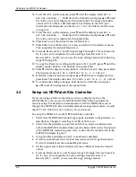
Page 28: ...to appropriate settings that conform to the rules above 4 3 Setup via HLP 4200WD Display This section provides instructions for setting up the HRR 4104 receiver module via the buttons and display of t...

Page 29: ...display reads RECEIVER A MUTE Hold down the Set button and press or until the value you want FORCED or UNFORCED is displayed then press Enter For details on the mute feature see Section 4 1 3 Mute on...

Page 30: ...ress or until YES is displayed then press Enter The display asks ARE YOU SURE COPY TO B C D YES NO 22 To confirm the settings changes hold down the Set button and press or until YES is displayed then...

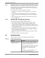
Page 31: ...are the leading source of poor performance in a broadband optical fiber network Dirty optical connectors lead to optical signal loss and reflections which in turn can seriously degrade carrier to noi...

Page 32: ...optic cleaning swab part number F1 25184 from Fiber Instrument Sales or similar and wet with high grade isopropyl alcohol 3 Insert the cleaning swab directly into the adapter until it fully touches th...

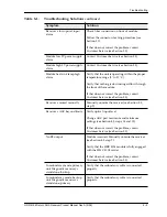
Page 33: ...Customer Service see Section 5 3 Receiver x muted manually Manually unmute the receiver see Section 4 3 step 9 Receiver x AGC beyond limits Verify optical input level Change AGC pad maximum and minimu...

Page 34: ...ting by Harmonic The use and purchase of this product does not convey a license under any patent rights copyrights trademark rights or any intellectual property rights of Harmonic Nothing hereunder co...

Page 35: ...operation of the product or software or firmware will be uninterrupted or error free 5 6 Limitations of Warranty The foregoing warranty shall not apply to defects resulting from abuse neglect by the B...

Page 36: ...Maintenance and Troubleshooting 5 6 Copyright 2005 Harmonic Inc...

Page 37: ...0 dB C IM31 60 dB RF output level2 45 dBmV per channel Operational bandwidth 5 to 100 MHz Flatness 5 to 70 MHz 0 5 dB 70 to 100 MHz 1 0 dB RF attenuator adjustment range 30 dB in 1 0 dB steps Impedanc...

Page 38: ...to 100 MHz 12 dB Impedance 75 Connector type Female F Network Management RS 485 RS 233C connectors in HLP 4200 A 4 Electrical Power requirements 24 VDC supplied by HLP 4200 bus Power consumption 15 W...

Page 39: ...ector A 8 Agency Certifications UL60950 CSA60950 cTUVus FCC Part 15 Class A EN60950 TUV GS mark EN 55022 EN55024 TUV EMC mark CE A 9 Compliance with WEEE Harmonic will ensure that all products that ca...

Page 40: ...Technical Specifications A 4 Copyright 2005 Harmonic Inc...

Page 41: ...c Way Sunnyvale CA 94089 U S A Tel 1 800 788 1330 inside U S Tel 1 408 542 2500 outside U S Fax 1 408 490 6708 Asia Pacific Headquarters Harmonic Limited Suite 703 704 CMG Asia Tower The Gateway 15 Ca...

Page 42: ...Harmonic Inc Offices B 2 Copyright 2005 Harmonic Inc...

Reviews: