Appendix F FLEX Decoding Module
Configuring the FLEX Module in NMX
© 2012 Harmonic Inc.
64
Electra 1000, Version 3.0, Rev M
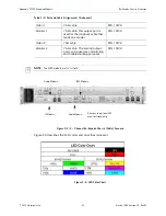
F.12.2 4 - Channel
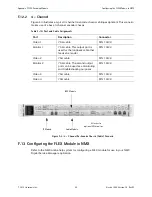
Figure F-4 illustrates a typical 4-channel re-encode chassis cabling assignment. This scenario
makes use of a base 4-channel encoder chassis.
Figure F-4: 4 - Channel Re-Encode Chassis (Cable) Scenario
F.13 Configuring the FLEX Module in NMX
Refer to the NMX online help system for configuring a FLEX module for use in your NMX
Digital Service Manager application.
Table F-10: Port and Cable Assignments
Port
Description
Connector
Video 1
75
Ω
cable
DIN 1.0/2.3
Monitor 1
75
Ω
cable. This output port is
used for the loopback cable that
feeds an encoder.
DIN 1.0/2.3
Video 2
75
Ω
cable
DIN 1.0/2.3
Monitor 2
75
Ω
cable. The second output
port can be used as a monitoring
and troubleshooting purposes.
DIN 1.0/2.3
Video 3
75
Ω
cable
DIN 1.0/2.3
Video 4
75
Ω
cable
DIN 1.0/2.3
IP Module
Audio Module
Attaches to
optional SDI monitor
FLEX Module


