Chapter 3 Installation
Cabling the Encoder
© 2012 Harmonic Inc.
24
Electra 1000, Version 3.0, Rev M
3.5
Cabling the Encoder
CAUTION:
Do not make any cable connections when the power cord is connected. You must unplug the
power cable to turn off the encoder.
The next sections describe how to connect the following cables:
Audio input
Video input
IP output
Ethernet management
Power
3.5.1
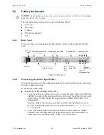
Back Panel
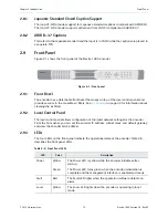
Figure 3-4 shows a sample back panel of the Electra 1000 encoder configured with AIC
cards.
Figure 3-4: Back panel
3.5.2
Connecting the Audio Input Cables
An encoder may have up to five audio input cards (AICs), each of which has two analog and
two stereo digital audio ports.
To connect the audio cables:
Connect one of the following audio sources:
Analog.
If you have an analog audio source, connect the audio cable with the Phoenix
1881367 connector
to the analog audio port, and connect the other end to the audio
source device. On the encoder, the analog ports are labeled “ANLG AUD1” and
“ANLG AUD2.”
Install the cable shield drain lug under the head of the AIC panel fastener screw.
For cable building information, refer to the pinout information in
Digital.
If you have a digital audio source, connect a coaxial cable with the BNC
connector from the digital audio port to the audio source. On the encoders, the
digital audio ports are labeled “DGTL AUD1” and “DGTL AUD2.”
AC Power
Fuse Cover
Audio Input Cards
Digital Audio Input Ports
Fault and
Locator LEDs
Fault
Relay
Port
Ethernet
Management Port
Ethernet
Output Ports
Plug
Video Input Ports
Analog Audio Input Ports
Expansion Slot


