background image

Modero G5 Touch Panels - Installation & Hardware Reference Manual

31

|   TOC

STEP 3: Secure the Touch Panel To the Backbox

The Backbox uses notches and tabs on the front edges (top and bottom) to secure the panel into place. Follow the steps below to 

install the panel into the Backbox, starting the upper edge of the touch panel:


Upper Tabs First

1. 

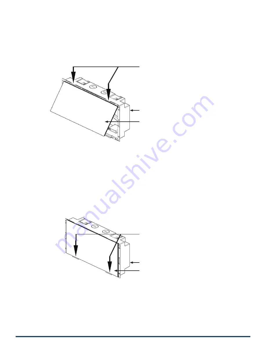
Center the top edge of the touch panel against the upper outside edge of the Backbox and latch the top of the panel onto the 

Backbox top-hooks (

FIG. 27

): 


2. 

Gently press the top edge of the touch panel into place to engage the panel’s notches and the top-hooks on the Backbox.


Lower Tabs - Gently Snap Into Place

1. 

Swing the bottom edge of the touch panel into position until it rests against the lower outside edge of the Backbox. 


NOTE: If a gap is observed between the panel and the Backbox, or binding is felt while locking down the panel, stop and verify 

there are no cables in the way. Do not force the panel into position, or the touch screen or the panel electronics may  

be damaged

2. 

Gently press the bottom edge of the panel gently but firmly and ONLY IN THE PLACES INDICATED BELOW until the tabs 

clickinto place to secure the panel (FIG. 28):


FIG. 28  Snapping the bottom edge of the panel into the Backbox


3.     Reconnect the terminal Ethernet and USB to their respective locations on either the Ethernet port or NetLinx Master.

FIG. 27  Engaging the top edge of the panel with the top hooks on the Backbox

Use the top-hooks on the top edge of the Backbox 

to latch the top of the touch panel into place

Plastic Backbox

MD-1002 Touch Panel

Plastic Backbox

MD-1002 Touch Panel

Gently press the bottom edge of the

touch panel in these places (simultaneously)

to snap the bottom edge of the panel into

place and secure the panel in the Backbox


SEE NOTES BELOW 

Observe the decal that is placed on the touch

panel (glass surface) to avoid pressing the glass

in the wrong places, which could result in

damage to the panel

Summary of Contents for MD-702

Page 1: ...UCH PANELS MD 702 7 MODERO G5 WALL MOUNT TOUCH PANEL MT 702 7 MODERO G5 TABLETOP TOUCH PANEL MD 1002 10 MODERO G5 WALL MOUNT TOUCH PANEL MT 1002 10 MODERO G5 TABLETOP TOUCH PANEL MT 2002 20 MODERO G5...

Page 2: ...ck or fire The exclamation point within an equilateral triangle is intended to alert the user to the presence of important operating and maintenance servicing instructions in the literature accompanyi...

Page 3: ...pment generates uses and can radiate radio frequency energy and if not installed and used in accordance with the instructions may cause harmful interference to radio communications However there is no...

Page 4: ...labeled in accordance with European Directive 2012 19 EU concerning waste of electrical and electronic equipment WEEE This label indicates that this product should not be disposed of with household w...

Page 5: ...002 Specifications 10 MT D 1002 10 1 G5 Touch Panels 12 MT 1002 Tabletop 12 MT 1002 Specifications 12 MD 1002 Wall Mount Landscape 14 MD 1002 Specifications 14 MD 1002 Dimensions 16 MT D 702 7 G5 Touc...

Page 6: ...1002 Cutout Dimensions 28 MD 702 Cutout Dimensions 28 STEP 2 Insert Connectors on the Touch Panel 30 STEP 3 Secure the Touch Panel To the Backbox 31 Lower Tabs Gently Snap Into Place 31 Removing the...

Page 7: ...lity The distinctive appearance will complement even the most sophisticated meeting facilities and homes With a lightning fast processor brilliant graphics and enhanced capabilities the Modero G5 is t...

Page 8: ...s Power Off Settings options Configuration and Programming G5 touch panels are equipped with a Settings menu that provides the ability to configure various features on the panels To access the Setting...

Page 9: ...ngerprints and dirt from the device This kit comes with cleaning cloths and a bottle of cleaning fluid specifically for use with the device When cleaning the device do not directly spray the device wi...

Page 10: ...Type TFT Active Matrix Color LCD with In plane Switching Technology IPS Display Size WH 20 4 x 9 5 519mm x 242mm 21 3 541mm diagonal Viewable Area WH 18 7 x 7 8 475mm x 198mm 20 3 514mm diagonal Reso...

Page 11: ...stment of the panel brightness Proximity Detector Max range 3 typ range 1 FOV 10 degrees Camera HD 720p camera for video conferencing video chat support LED Indicators Camera active indicator Sleep Bu...

Page 12: ...1 AS NZS CISPR 32 Class B IC CISPR 22 Class B UL 60950 1 VCCI CISPR 22 Class B RoHS WEEE Touch Screen Display Display Type TFT Active Matrix Color LCD Display Size WH Landscape 9 1 x 5 9 230mm x 149m...

Page 13: ...ex VoIP SIP v2 0 Graphics Engine AMX G5 G5 enhanced feature set supporting multi touch and gestures scrolling transitions applications See TPD5 Operations Guide for more information Embedded Applicati...

Page 14: ...box Power Consumption Full On 14 5 W Standby 5 8 W Shutdown 1 W Start Up Inrush Current Not applicable due to PoE standard External Power Supply Required Optimal performance requires use of one of the...

Page 15: ...720p at 25 fps decode only Supported Video Transport Streams MPEG TS for MPEG2 and H 264 HTTP for MJPEG Max Number of Active Video Streams 2 720dpi 30fps Audio Microphone 42 dB 3 dB sensitivity FET mi...

Page 16: ...nt Kit for use with MSD 1001 L2 RMBK 1001 FG2265 36 MSA RMK 10 Rack Mount Kit for 10 Modero Wall Mount Touch Panel FG2265 14 MXA MPL Modero Multi Preview Live FG5968 10 PS POE AT TC PoE Injector 802 3...

Page 17: ...0950 1 VCCI CISPR 22 Class B RoHS WEEE Touch Screen Display Display Type TFT Active Matrix Color LCD with Fringe Field Switching FFS Wide viewing angle technology Display Size WH Landscape 7 3 x 4 8 1...

Page 18: ...5 G5 enhanced feature set supporting multi touch and gestures scrolling transitions applications See TPD5 Operations Guide for more information Embedded Applications Viewer Applications PDF JPEG BMP P...

Page 19: ...Backbox Power Consumption Full On 14 5 W Standby 5 8 W Shutdown 1 W Start Up Inrush Current Not applicable due to PoE standard External Power Supply Required Optimal performance requires use of one o...

Page 20: ...up to 720p at 25 fps decode only Supported Video Transport Streams MPEG TS for MPEG2 and H 264 HTTP for MJPEG Max Number of Active Video Streams 2 720dpi 30fps Audio Microphone 42 dB 3 dB sensitivity...

Page 21: ...MSA AMK2 07 Any Mount Kit for 7 Modero Wall Mount Touch Panel FG2265 35 MSA RMK 07 Rack Mount Kit for Modero Touch Panel 7 FG2265 15 MXA MPL Modero Multi Preview Live FG5968 10 PS POE AT TC PoE Inject...

Page 22: ...ded 2 pin 3 5mm captive wire connector included with the device This connector is retained within its port with locking screws instead of the pins on each side of standard captive wire connectors and...

Page 23: ...located on the bottom of the device FIG 15 FIG 15 MT 2002 underside connectors NOTE Refer to the Power via 12V section on page 32 for details on wiring a power connection The underside USB port as we...

Page 24: ...ons drawings for the MT 702 are available to download from www amx com Connector Locations USB peripherals mouse keyboard etc may be connected to the USB port on the rear of the device Updates to the...

Page 25: ...and or cooling approaches that must be taken into consideration to maintain the product within the specified operating temperature FIG 18 shows an AMX device installed in a wall with a filled volume...

Page 26: ...Rough In Boxes Refer to the Quick Start Guide included with each mounting kit for instructions Plastic Backbox Modero wall mount panels comes with a clear plastic Backbox This Backbox can be used to...

Page 27: ...e The outside edges of the template are the same dimensions as the touch panel which allows you to troubleshoot possible conflicts with wall edges doors and other potential obstacles The Modero instal...

Page 28: ...s a margin of error if the opening needs to be expanded Too little wall material removed is always better than too much MD 1002 Cutout Dimensions FIG 23 MD 1002 Cutout Dimensions MD 702 Cutout Dimensi...

Page 29: ...king tabs are the primary method for securing the Backbox to the wall To ensure a stable installation the thickness of the wall material must be a minimum of 50 inches 1 27cm and a maximum of 875 inch...

Page 30: ...x is clear to allow visual confirmation that the tabs have been extended and are gripping the wall as well as in assisting with removal if necessary STEP 2 Insert Connectors on the Touch Panel 1 Befor...

Page 31: ...el stop and verify there are no cables in the way Do not force the panel into position or the touch screen or the panel electronics may be damaged 2 Gently press the bottom edge of the panel gently bu...

Page 32: ...r other hand to stabilize the front of the touch panel Always pull on the panel s plastic bezel NEVER pull on the glass edge FIG 30 3 With the bottom edge of the panel free carefully lift up and out t...

Page 33: ...onnection failure instantly if it is not Without using the ping feature a connection may still be attempted but a failure will take longer to be recognized NOTE If you are trying to connect to a Maste...

Page 34: ...conference rooms classrooms network operation command centers homes hotels entertainment venues and broadcast facilities among others AMX is part of the HARMAN Professional Group the only total audio...

Reviews: