32
Hardware Reference Guide - NX-Series NetLinx Integrated Controllers
Wiring and Connections
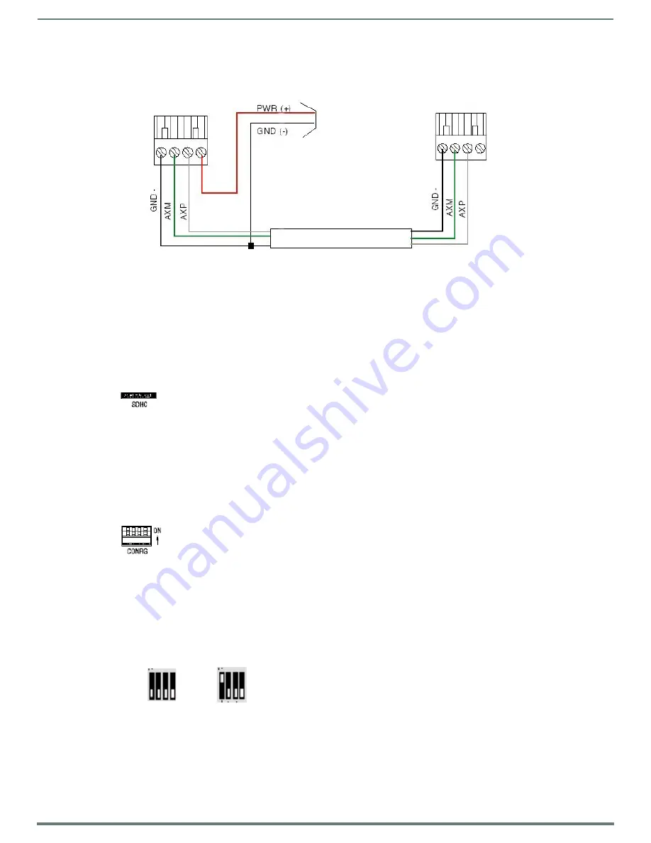
To use the 4-pin 3.5 mm mini-Phoenix (male) captive-wire connector for data communication and power transfer, the incoming
PWR and GND cable from the 12 VDC-compliant power supply must be connected to the AxLink cable connector going to the
central controller. FIG. 28 shows the wiring diagram:
FIG. 28
4-pin mini-Phoenix connector wiring diagram (using external power source)
CAUTION:
When you connect an external power supply, do not connect the wire from the PWR terminal (coming from the external
device) to the PWR terminal on the Phoenix connector attached to the Controller unit. Make sure to connect only the AXM, AXP, and
GND wires to the Controller’s Phoenix connector when using an external power supply.
Make sure to connect only the GND wire on the AxLink/PWR connector when using a separate 12 VDC power supply. Do not
connect the PWR wire to the AxLink connector’s PWR (+) opening.
SDHC Card Slot
The NX-3200 and NX-4200 each feature an externally accessible SDHC card slot.
NOTE:
The card slot is reserved for future use. Do not install a card in the card slot at this time.
FIG. 29 displays the SDHC card slot.
FIG. 29
SDHC Card Slot
Configuration DIP Switch
The NX-series controllers each have a configuration DIP switch which allows for certain operations to occur during boot-time. The
DIP switch positions are assigned as follows:
Switch for Program Run Disable
Switch for Boot from External SD Card (only applicable to the NX-3200 and NX-4200.)
NOTE:
The Configuration DIP Switch is located on the front panel of the NX-1200 and not the rear panel.
FIG. 30 displays the Configuration DIP Switch for the NX-series controllers.
FIG. 30
Configuration DIP Switch
Program Run Disable (PRD) Mode
You can use the Configuration DIP switch to set the on-board Master to Program Run Disable (PRD) mode. PRD mode prevents the
NetLinx program stored in the on-board Master from running when you power up the Integrated Controller. You should only use
PRD mode when you suspect the resident NetLinx program is causing inadvertent communication and/or control problems.
If necessary, place the on-board Master in PRD mode and use the NetLinx Studio program to resolve the communication and/or
control problems with the resident NetLinx program. Then download the new NetLinx program and try again.
FIG. 31 displays the default DIP switch settings and the settings for PRD mode. To switch to PRD mode, move the position 1 DIP
switch to ON.
FIG. 31
DIP Switch settings - PRD mode
NOTE:
Consider equating PRD Mode to a PC’s SAFE Mode setting. With PRD mode, you can continue to power a unit, update the
firmware, and download a new program while circumventing any problems with a currently downloaded program. You must power
cycle the unit after activating/deactivating PRD mode on Program Port DIP switch #1.
Top view
Top view
To the Controller’s
AxLink/PWR connector
To the external AxLink device
Local 12+ VDC
power supply
(coming from an
external
power supply)
Default mode
PRD mode


