pg. 24
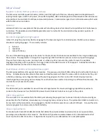
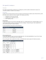
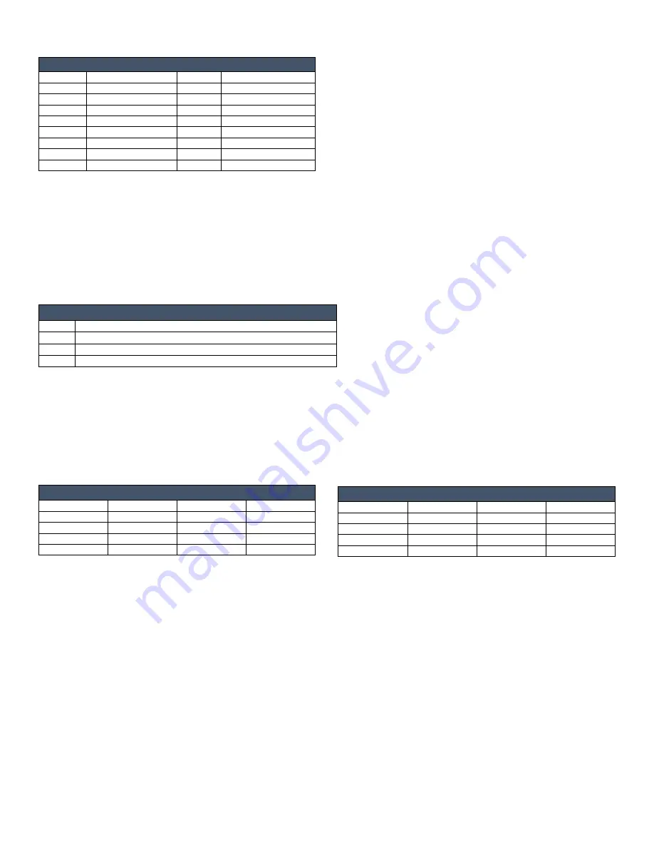
Relay Ports
Relay Pinout
Signal
Function
Signal
Function
1A
Relay 1 Common
1B
Relay 1 NO
2A
Relay 2 Common
2B
Relay 2 NO
3A
Relay 3 Common
3B
Relay 3 NO
4A
Relay 4 Common
4B
Relay 4 NO
5A
Relay 5 Common
5B
Relay 5 NO
6A
Relay 6 Common
6B
Relay 6 NO
7A
Relay 7 Common
7B
Relay 7 NO
8A
Relay 8 Common
0B
Relay 8 NO
•
Connectors are labeled A and B
•
These relays are independently controlled, isolated and normally open
•
The relay contacts are rated for a maximum of 1 A @ 0-24 VAC or 0-28 VDC (resistive load)
•
If desired, a metal connector strip is provided to distribute ‘common’ among multiple relays.
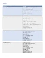
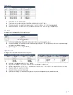
I/O Ports
Configurable as voltage sensing or digital output
I/O – Pinout
Signal
Function
GND
Signal Ground
1-4
Individually configurable I/O
+12vdc
Vcc
•
Each pin is individually configurable as a voltage sense input or a digital output
•
Threshold settings are available to determine the high/low points for the digital input and the required voltage
change to generate an update
•
Digital Output can push or pull 100mA
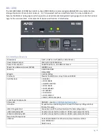
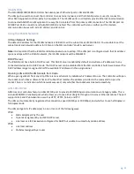
IR/SERIAL Port
Configurable as IR control emulation or 1-way serial
IR/S Port Pinout – MU-2300 & MU-3300 lower port
Signal
Function
Signal
Function
1-
IR 1 GND
3-
IR 3 GND
1+
IR 1 Signal
3+
IR 3 Signal
2-
IR 2 GND
4-
IR 4 GND
2+
IR 2 Signal
4+
IR 4 Signal
•
Each pair is configurable as IR or 1-way RS-232
•
Baud rates for RS-232 are limited. Maximum Baud is 19200 in DATA mode
•
RS-232 voltages are 0-5v, not +-12v. This limits the maximum distance based on the cable resistance to <10 ft
•
IR carrier frequency up to 1.142 MHz
•
All ports can be used simultaneously
•
These ports accept an IR Emitter (CC-NIRC) that mounts onto the device's IR receiver window
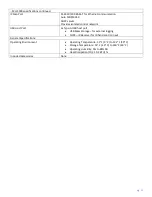
IR/S Port Pinout – MU-3300 upper port
Signal
Function
Signal
Function
5-
IR 5 GND
7-
IR 7 GND
5+
IR 5 Signal
7+
IR 7 Signal
6-
IR 6 GND
8-
IR 8 GND
6+
IR 6 Signal
8+
IR 8 Signal

