background image

11

INSPECTION AND INSTALLATION

UNPACKING AND INSPECTION

Your  1605/1603  was  carefully  packed  at  the  factory,  and  the  container  was  designed  to  protect  the  unit  from  rough  handling.
Nevertheless, we recommend careful examination of the shipping carton and its contents for any sign of physical damage which
could have occurred in transit.

If damage is evident, do not destroy any of the packing material or the carton, and immediately notify the carrier of a possible claim
for damage.  Shipping claims must be made by the consignee.

The carton should contain:

Model 1605/1603 Music Mixer.

Mains Cable

UREI Instruction Manual (this book).

Warranty Card (the serial number tag is on the base panel of the Mixer).

2mm Allen key

ENVIRONMENTAL CONSIDERATIONS

The 1605/1603 Mixer will operate satisfactorily over a range of ambient temperatures from 0 C to +50C (+32F to +122F), and up to
80% non-condensing relative humidity.

If the system is installed in an equipment rack, console or desk with high heat producing  equipment (such as power amplifiers),
adequate ventilation should be provided in order to assure longest component life.  Also, while circuitry susceptible to hum pick-up
is sufficiently shielded from moderate electromagnetic fields, installation should be planned to avoid mounting the system immediately
adjacent to large power transformers, motors, etc.

POWERING

The 1605/1603 may be operated from 100-250V AC mains (50-60 Hz, single phase). BE SURE TO VERIFY LINE VOLTAGE
BEFORE CONNECTING THE 1605/1603 TO THE MAINS.

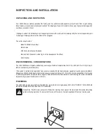
Please Note. The IEC mains connector is fitted with a retaining clip to prevent the mains lead from accidentally being
pulled out during operation.  To ensure that this clip will fit correctly, the lead supplied with the mixer must be used.

Summary of Contents for 1605

Page 1: ...Music Mix Music Mix Music Mix Music Mix Music Mixer er er er er User Guide User Guide User Guide User Guide User Guide...

Page 2: ...ment on the part of the vendor Soundcraft shall not be liable for any loss or damage whatsoever arising from the use of information or any error contained in this manual No part of this manual may be...

Page 3: ...INSPECTION AND INSTALLATION 11 MAKING ADJUSTMENTS AND FITTING SPARES 12 MOVING THE REAR CONNECTOR PANEL 14 REPOSITIONING THE RACK EARS 14 ENABLING THE EXTERNAL MUTE FEATURE 14 CONNECTING TO A TYPICAL...

Page 4: ...nto your outlet consult an electrician for replacement of the obsolete outlet Protect the power cord from being walked on or pinched particularly at plugs convenience receptacles and the point where t...

Page 5: ...e objects filled with liquids such as vases on the apparatus No naked flame sources such as lighted candles should be placed on the apparatus Ventilation should not be impeded by covering the ventilat...

Page 6: ...within an equilateral triangle is intended to aler is intended to aler is intended to aler is intended to aler is intended to alert the user to the pr t the user to the pr t the user to the pr t the...

Page 7: ...ecommends AKG Professional Dj Headphones Please visit www akg com dj for more information Welcome Thanks for purchasing a UREI by Soundcraft 1603 1605 mixer we hope you get just as much joy from using...

Page 8: ...rnal circuitry may result Likewise on all balanced inputs avoid sources with large common mode DC AC or RF voltages as these will reduce the available signal range on the inputs Note that OdBu 0 775V...

Page 9: ...ack to the star point Equipment which has balanced unbalanced inputs and outputs may need to be electrically isolated from the equipment rack and or other equipment to avoid earth loops AUDIO WIRING H...

Page 10: ...ons are not being infringed WORKING SAFELY WITH SOUND Although your new console will not make any noise until you feed it signals it has the capability to produce sounds which when monitored through a...

Page 11: ...erate satisfactorily over a range of ambient temperatures from 0 C to 50C 32F to 122F and up to 80 non condensing relative humidity If the system is installed in an equipment rack console or desk with...

Page 12: ...o adjust the input level to individual channels e g to reduce the input when using a piece of equipment with a high output level There are 2 pads on each of the input channels The 14dB gain stage swit...

Page 13: ...ws removed earlier DO NOT OVER TIGHTEN THE SCREWS Replacing The Cross Fader Using a pozi screwdriver undo and remove the screws which secure the fader mounting plate to the subframe Carefully withdraw...

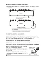
Page 14: ...er A user provided external mute switch must be wired between the two rear panel contacts as shown MOVING THE REAR CONNECTOR PANEL It is possible to move the rear connector panel from its factory defa...

Page 15: ...15 CONNECTING TO A TYPICAL SOUND SYSTEM The diagram below shows how to connect the different parts of a typical sound system...

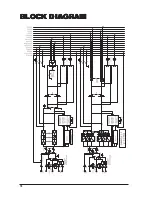
Page 16: ...16 BL BL BL BL BLOCK DIA OCK DIA OCK DIA OCK DIA OCK DIAGRAM GRAM GRAM GRAM GRAM...

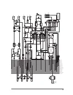
Page 17: ...17...

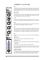
Page 18: ...witch is not selected this LED will flash if the eternal mute is activated This shows that the mic is now routed to the master outputs Phone Line This switch is a push on push off type It routes the s...

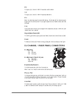
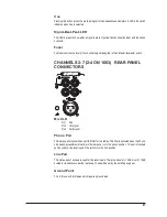
Page 19: ...s signal being fed to the master buses left and right DJ CHANNEL 1 REAR PANEL CONNECTORS DJ Mic XLR Pin 1 Gnd Pin 2 Hot signal Pin3 Cold signal DJ Mic Insert Point 1 4 jack Tip Send signal Ring Retur...

Page 20: ...he Aux buses This means that the signal level sent to the aux buses does not depend on the position of the channel s fader When the pre switch is in the up position a post fade signal is sent to the a...

Page 21: ...S Mic XLR Pin 1 Gnd Pin 2 Hot signal Pin3 Cold signal Phono Pair This stereo pair of sockets has an RIAA filter for turntables This filter is activated when the Phono Line switch accessible via the ho...

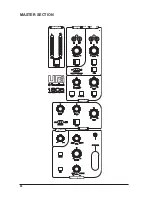
Page 22: ...22 MASTER SECTION...

Page 23: ...nit The signal can be monitored via its cue switch The signal is controlled via the on switch note that the cue switch is before the on switch in the signal path The level of the signal is controlled...

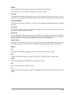
Page 24: ...dphones EQ The single eq pot varies the headphones between dark and bright characteristics Dark treble cut and Bright bass cut Balance Pot The balance pot allows adjustment of the left right balance o...

Page 25: ...ypassing all level controls and eq controls Its level is set only by the pre set level control underneath the top fascia The channel 1 mic signal will be shown on the meters The channel 1 mic signal w...

Page 26: ...put level 20dbu Input impedance 45k ohms Rear Panel Connector connections XLR INPUT OUTPUT 3 pin female XLR Pin 1 Ground Pin 2 Signal Hot Pin 3 Signal Cold INSERT SEND and RETURN 1 4 TSR Jack MIC 1 On...

Page 27: ...rk 95dB FX Sends offness 90dB Input and Output Impedance Mic Input 2k ohms Line Input 45k ohms Aux Input Unbalanced RCA Phono 30k ohms Master booth Output 75 ohms Aux Output 75 ohms Headphones Output...

Page 28: ...The cartridge is usually fitted to a removable headshell that plugs into the turntable arm Clipping The harsh distorted sound that results when the signal hits the maximum level possible Contour Law C...

Page 29: ...lly less than 100 ohms Low Z sources are less prone to interference pickup Inputs are usually high impedance High Z so that one source can connect to more than one channel without signal loss Note tha...

Page 30: ...is returned through a channel and replayed by pressing a trigger Many samplers provide creative effects such as repeat and reverse The UREI sampler is BPM activated Scratching The art of rhythmically...

Page 31: ...t in transit both to and from the Dealer or Soundcraft and postage must be prepaid 4 This warranty shall only be available if a the Equipment has been properly installed in accordance with instruction...

Page 32: ...32...
Reviews: