background image

Harman®  •  Allure50 Owner’s Manual_R24  •  2016 -___  •  03/21

14

3-90-888000c

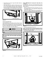
•  Lift off the clean-out cover to open the bottom clean-out 

chamber. Figure 2.5

•  Clean ash buildup from inside the chamber while cover 

is off. Use the scraper to tap on the top front edge of the 

burn pot. This will help knock pieces of ash, loosened by 

the scraping process, down through the holes. It also helps 

knock ash buildup from the igniter element and bracket.

Clean Ash Accumulation

Figure 2.5

Cleaning Igniter Bracket-

C

heck  cleanliness  of  the  igniter  and  inner  burnpot.  If  the 

igniter has ash buildup it must be removed to insure proper 

ignition. Use the provided brush to remove ash buildup from 

in and around the igniter. Once ash is loose vacuum around 

igniter and at the base of burn pot. Figure 2.6.

Note: The hot lead/cold lead connection must always 

be pulled to the rear of the feeder body before 

operation.

Use caution when cleaning burn pot clean-out 

chamber. Do not damage the high temperature igniter 

wires.

WARNING

!

Clean Ash Accumulation

Figure 2.6

Yearly Maintenance: 

Cleaning the Combustion Fan 

Chamber-

The combustion inlet cover is located behind the ash pan 

that must be removed to properly clean the combustion fan 

blade. Figure 2.7.

•  Remove combustion inlet cover by pulling up on cover. 

This  allows  access  to  the  combustion  fan  blade  and 

exhaust path. Figure 2.7.

•  Remove any flyash or debris that has collected around 

combustion fan blade with the provided paint brush.

Figure 2.7

Exhaust Passage

Combustion Fan Blade

Combustion Inlet Cover

•  Clean exhaust passage. Figure 2.8.

NOTE: The ESP Sensor is located just inside the exhaust 

passage. Be sure not to damage the ESP Sensor while 

cleaning the exhaust passage.

•  Once cleaned replace combustion inlet cover and ashpan.

Figure 2.8

Exhaust Passage

Combustion Fan Blade

ESP Sensor

Summary of Contents for 1-90-888000-1

Page 1: ...l down WARNING Please read this entire manual before installation and use of this pellet fuel burning room heater Failure to follow these instructions could result in property damage bodily injury or...

Page 2: ...ion extended beneath the flue pipe when installed with horizontal venting Floor Protection USA CANADA Sides A 6 152 mm Back B 1 25 mm Front C 6 152 mm Alcove Installation Min Alcove Height 42 1067mm M...

Page 3: ...etime Warranty 22 C Loss of Power 24 D Emergency Manual Ignition 24 E Troubleshooting 25 F Glass Installation and Cleaning 26 G Contact Information 28 1 Product Specifications and Important Safety Inf...

Page 4: ...erate this wood heater in a manner inconsistent with operating instructions in this manual Risk of Fire Hearth Home Technologies disclaims any responsibility for and the warranty and agency listing wi...

Page 5: ...ore information or visit www hpba org safety information To prevent unintended operation when not using your stove for an extended period of time summer months vacations trips etc Unplug stove from re...

Page 6: ...hut down the stove and evacuate the residence Before using the appliance have the venting system thoroughly inspected and replace any damaged components With any hearth appliance installation of smoke...

Page 7: ...r fuel will void your warranty CAUTION Do not burn fuel that contains an additive May cause hopper fire Damage to product may result Read the list of ingredients on the packaging WARNING Tested and ap...

Page 8: ...ll hopper with pellets Initial start up Only 1 Select Language 3 Adjust arrows to set room desired temperature 4 Touch the On Off Power Icon Refer to Touch Manual for all other operations Please Note...

Page 9: ...re has tall flames with black tails and is lazy The feed rate needs to be reduced or the burnpot needs cleaning Heat exchanger or exhaust blower needs cleaning Smoky start up or puffs of smoke from th...

Page 10: ...per If you did not fill hopper The message will disappear in 30 seconds Replace the 2 AA batteries in the Wireless Remote Sensor If Wireless Remote Sensor batteries die the Back Up Sensor will continu...

Page 11: ...TE THE STOVE MUSTBE COMPLETELYOUTBEFORE YOU VACUUM THE STOVE LIVE PELLET EMBERS IF SUCKED INTO THE VACUUM WILL LIGHT THE VACUUM ON FIRE AND MAY ULTIMATELY CAUSE A HOUSE FIRE Follow the detailed instru...

Page 12: ...ashes into a steel non combustible container with tight fitting lid outside Use provided paint brush Vacuum loose ash from around igniter and inside burn pot Stove MUST be turned off cold and unplugge...

Page 13: ...ing Glass Once unit is cold use a non abrasive glass cleaner on glass and wipe clean Scrape and Vacuum Heat Exchanger Cleaning the Heat Exchanger Clean the heat exchanger with scraper as shown in Figu...

Page 14: ...nnection must always be pulled to the rear of the feeder body before operation Use caution when cleaning burn pot clean out chamber Do not damage the high temperature igniter wires WARNING Clean Ash A...

Page 15: ...ances Wash the surface with cool water and rinse thoroughly You may wish to use a non abrasive cleaner specifically designed for use on stove glass In any case dry thoroughly before relighting your st...

Page 16: ...g Manufacturing Date Aug 2016 Ending Manufacturing Date Active Part number list on following page Pellet Stove 03 21 1 2 3 4 5 6 7 8 10 11 12 13 14 15 16 17 18 19 20 21 22 9 1 90 888001 1 Black w Wire...

Page 17: ...n Pot Tailpipe Pkg of 5 Sets 1 00 07381 Y 10 Feeder Assembly See following Page 11 Combustion Blower Capacitor 1 00 02275 Y Capacitor 1 00 00276 Y Blower Mounting Studs and Nuts 5 Sets 1 00 832150 12...

Page 18: ...1 00 02000 1 1 3 Complete Latch 2 Sets 1 00 0669697 Y 1 4 Gasket 3 8 x 1 2 20 Feet 1 00 375501 1 5 Ball Plunger 5 16 x 1 2 Pkg of 3 3 31 5500 3 1 6 Push Retainer 5 16 Pkg of 100 3 31 94807 100 1 7 Hi...

Page 19: ...m your dealer or distributor Stocked at Depot ITEM DESCRIPTION COMMENTS PART NUMBER 5 1 Front Weldment 1 10 888515W 5 2 Glass Clips Pkg of 4 SRV8000 031 Y 5 3 Glass w Gasket 1 00 888150 Y 5 4 Gasket 1...

Page 20: ...3 Feed Cover Gasket 2 Sets 1 00 677122 Y 10 4 Pusher Arm 1 10 888539W Y Pillow Block Pkg of 4 3 31 3614087 4 Y 10 5 Auger 3 50 00565 Y Gasket Auger Pkg of 5 1 00 888196 10 6 Bearing Retainer w Hardwar...

Page 21: ...88857 28 Gloss Red 1 00 88857 29 Satin Black 1 00 88857 1 Side Panel Right Brushed Stainless 1 00 88877 6 Gloss Black 1 00 88877 26 Gloss White 1 00 88877 28 Gloss Red 1 00 88877 29 Satin Black 1 00...

Page 22: ...r whichever occurs earlier However the Warranty coverage shall commence no later than 24 months following the date of Product shipment from HHT regardless of the installation or occupancy date The ter...

Page 23: ...such as exhaust fans or forced air furnaces or other such causes 6 use of fuels other than those specified in the operation instructions 7 installation or use of components not supplied with the appl...

Page 24: ...will not rise The unit will then shut down and may flash a six blink status error See ESP error codes If the fire is still burning it will resume normal operation Contact your dealer if you have ques...

Page 25: ...as failed Partially burned pellets Feed rate too high Poor air to fuel mixture Check burn pot clean out cover and air intake Burn pot may need to be cleaned Combination of all the above Smoke smell Se...

Page 26: ...with no glass Door must be slightly open Insert right column from the side While holding column to the door swing door open and install 3 10 24 x 3 8 Button Head Screws at the top center and bottom o...

Page 27: ...Harman Allure50 Owner s Manual_R24 2016 ___ 03 21 27 3 90 888000c...

Page 28: ...___ ________________________________________________________________________________ ________________________________________________________________________________ __________________________________...

Reviews: