background image

Service Manual

JBL Bar 2.1 Deep Bass

2.

1

CH TV Sounbar

SKU:

JBL2GBAR21DBBLKAM

JBLBAR21DBBLKEP

JBLBAR21DBBLKUK

JBLBAR21DBBLKAS

JBLBAR21DBBLKCN

JBLBAR21DBBLKBR

JBLBAR21DBBLKIN

SPECIFICATIONS:

Power supply: 100 - 240V~, 50/60Hz


Total maximum power : 300 W

Soundbar maximum output power: 2 x 50 W 

Subwoofer maximum power: 200 W

USB: 5V CC/0.5 A

Frequency response : 40Hz - 20KHz


Soundbar dimensions (W x H x D) : 965 x 58 x 85(mm) / 38" x 2.28" x 3.35"

Soundbar weight: 2.61 kg

Subwoofer dimensions (W x H x D) : 240 x 240 x 379(mm) / 8.9" x 8.9" x 14.6"

Subwoofer weight: 5.67 kg

Rev. 1.0    

Jun.

/2019

Released by Global Quality 2019

harman/kardon, Inc.

CONTENTS

Safety Instruction ...................................................................................... 2
Special Information BGA IC & Flat Pack-IC................................................


Software upgrade Instruction & Reset Procedure  ....................................8
Disassembly Instruction


............................................................................


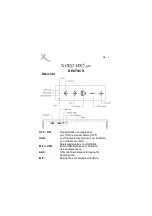
Block Diagram.......................................................................................... 11 

Circuit Diagarms & PCBA Layout


............................................................


1

4

Mechanical Exploded View  ......................................................................2

7

Revision List ............................................................................................ 

3

1

Spare Parts List ....................................................................................... 


2

9

Wiring Diagram..........................................................................................1

3

Summary of Contents for JBL Bar 2.1 Deep Bass

Page 1: ...ponse 40Hz 20KHz Soundbar dimensions W x H x D 965 x 58 x 85 mm 38 x 2 28 x 3 35 Soundbar weight 2 61 kg Subwoofer dimensions W x H x D 240 x 240 x 379 mm 8 9 x 8 9 x 14 6 Subwoofer weight 5 67 kg Rev...

Page 2: ...2...

Page 3: ...3...

Page 4: ...4...

Page 5: ...pter wo kshop n For additional questions please con d y u l epair helpdesk 5 How to Remove Install Flat Pack IC 1 Removal With Hot Ai Flat Pack IC Des Ide ing Machine 1 Prepa e the hot air flat pack I...

Page 6: ...of the flat pack IC and heat up Then move glue willbe mel d Fig S 1 4 Release the flat pack IC from the CBA using twe e Fig S 1 6 With Iron Wi 1 Using desolderingbraid remove the Ider from all pins o...

Page 7: ...S 1 7 P s Ide CBA Fig S 1 8 Instructions for Handling Semi conductors Electros tic breakdown of the semi conducto may occu due to a potential dif nee caused by electros tic cha e during unpacking or r...

Page 8: ...opy the upgrade file JBL_Soundbar_21 HUI to the root of USB disk and insert the USB disk into the USB port of soundbar Step2 Soundbar connect the power and enter operation mode Step3 press and hold th...

Page 9: ...b1 Take out the Main board of soundbar a Tools OR Disassembly procedure 9...

Page 10: ...b2 the iron grill b3 the Speakers or the VFD display panel OR b4 the subwoofer boards and speaker 10...

Page 11: ...AUDIO_MUTE 9 10 29 9 10 I2S_BCK I2S_DATA_RCH TW WF I2S_LRCK 14 12 13 LTW 25W 6 THD 1 LWF 25W 6 THD 1 AMP TAS5825M 15 16 45 46 48 44 AMP_WARN AMP_PDN 11 17 AMP_FAULT AUDIO_MUTE 9 10 28 9 10 I2S_BCK I2S...

Page 12: ...PWM_M PWM P 5 6 DAP TAS5534 LINK_LED PAIR 8 7 I2S_BCK I2S_DATA I2S_LRCK 15 13 14 M_I2C_SDA I2S_MCLK 11 3 3V M_I2C_SCL 5 A3 3V 6 A12V 34V PW_LOW SWITCH RX Module AVMD5100 Avrena 5 8G LED1 PW_LOW 0 RX...

Page 13: ...WIRING DIAGRAM 13 13...

Page 14: ...ICAL_IN C3P_TX C3P_RX HDMI_SPDIF HDMI_SDA HDMI_SCL BT_POWER_ON I2S_OUT_LRCK I2S_OUT_BCK LED_DRIVER_SPI_CLK_2 LED_DRIVER_SPI_MOSI_2 LED_DRIVER_SPI_CS_2 WIRELESS_TX_I2C_SCL WIRELESS_TX_I2C_SDA AMP_SCL A...

Page 15: ...A SDIN SCLK LRCLK GPIO2 GPIO1 GPIO0 GND U5 C121 C122 HS1 R98 R184 Q4 Q5 R51 R53 AMP_SDA AMP_SCL AMP_23V AMP_PDN FAULT AMP_MUTE AMP_23V AMP_23V I2S_OUT_LRCK I2S_OUT_BCK I2S_LCH_TW WF_DATA AMP_PDN FAULT...

Page 16: ...6 97 98 99 100 101 102 103 104 105 106 107 108 109 110 111 112 113 114 115 116 117 118 119 120 121 122 123 124 125 126 127 128 129 EP92A2E 104 1UF 2K 2K 10K 1UF 0 1 2 3 4 5 6 10K 10K 1K 470 330 FB120...

Page 17: ...Main Board LAYOUT DIAGRAM 17 17...

Page 18: ...Main Board LAYOUT DIAGRAM 18 18...

Page 19: ...LED2 4E LED2 4F LED2 5L LED2 5M LED2 5J LED2 5K LED2 5N LED2 5H LED2 5C LED2 5D LED2 5A LED2 5B LED2 5G LED2 5G1 LED2 5E LED2 5F LED2 A B C D E F G G1 H J K L M N DP DIG1 DIG2 DIG3 DIG4 DIG5 1 2 3 4 5...

Page 20: ...B 1K L303 FB 1K L304 FB 1K 1 2 3 4 5 6 7 CN301 POWER_KEY SOURCE_KEY VOLUME_DOWN VOLUME_UP 1 1 2 2 JK1 CN1 C310 R310 CN310 R311 SW310 L310 LED310 LED311 TO AMP BOARD LINK_LED1 WHITE LINK_LED ORANGE PAI...

Page 21: ...C_START DVDD GND GND GND GND AVDD INPUT_C INPUT_D FAULT OTW CLIP M1 M2 M3 GVDD_CD BST_D BST_C GND GND OUT_D OUT_D PVDD_CD PVDD_CD PVDD_CD OUT_C GND GND OUT_B PVDD_AB PVDD_AB PVDD_AB OUT_A OUT_A GND GN...

Page 22: ...Subwoofer AMP Board LAYOUT DIAGRAM 22 22...

Page 23: ...9 47R 1 2 CON2 2P 2 54 C11 104 50V R18 68R C16 102 200V HV 9 11 8 T1B 400UH NTC2 NC 1 1 2 2 3 3 4 4 D D C C B B A A Title Number Revision Size A4 Date 2019 3 26 Sheet of File G PW2009 37 REV1 0 A7 Sch...

Page 24: ...Soundbar Power Board LAYOUT DIAGRAM 24 24...

Page 25: ...B 2 GND 4 U1 R36 20K SF5887SG R11 43 2K R38 7 5K C13 50V 100PF ZD1 0R R17 NC NC 0 6 6MM J1 C17 100V 1NF R37 68R C18 100V 1NF 400UH 55UH R29 10R 8 9 1 1 2 2 3 3 4 4 D D C C B B A A Title Number Revisio...

Page 26: ...Subwoofer Power Board LAYOUT DIAGRAM 26 26...

Page 27: ...107000067 LED PCBA E04 403000601 power PCBA E05 104000418 5 8GHz Wireless TX module M01 201004462 Top cover M02 204003740 Silicone button M03 201004463 Back cabinet M04 113000265 Tweeter 6 30W M05 200...

Page 28: ...2 Subwoofer Power PCBA E08 404002432 AC SOCKET PCBA E09 402002177 PAIR PCBA E10 404002459 Subwoofer AMP PCBA M11 105001472 wood case M12 405001078 SW Air tube top M13 201004476 plastic Pair button M14...

Page 29: ...4A ESOP 8 BAR2 0 2 1 U3 U12 112000381 IC SY8120B1ABC DC DC BAR2 0 2 1 U18 112000261 IC IA6005 33 SOT23 5 BAR2 0 2 1 IC1 IC107 112000361 IC IA6003 33S89F SOT 89 BAR2 0 2 1 U4 112000330 IC WS4603E LOAD...

Page 30: ...1 M02 204003740 SILICONE BUTTON BAR2 1 M15 204003591 SILICONE SHEET BAR2 1 M12 405001079 SW AIR TUBE TOP BAR2 1 M13 201004476 PLASTIC PAIR BUTTON BAR2 1 M18 201004477 PLASTIC FOOT BAR2 1 M14 20000193...

Page 31: ...Revision List Version1 0 Initial Release June 2019 31...

Reviews: