background image

30

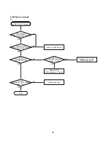
ELECTRICAL TROUBLESHOOTING GUIDE

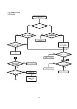
No 5V_D

or 5V_A .

No 5.2VA.

Is 5.2VA section working?

(Is the POWER CTL at

Pin6 High/low?)

Is oscillation present at the
Base of Q108?

Replace Q108.

Check L103, C123, C124,

R124.

Replace R102.

Replace BD101.

(Bridge rectifier)

Is R102(100K/2W) normal?

Is about AC 100V app;ied to

IC101 Pin 5.

Check IC101.

Is 5.2V applied to IC102
Pin 1?

Is there a DC voltage at the

(+) terminal of BD101?

Check R127, 128.

(SHUTDOWN CKT)  

1. Power(SMPS) Circuit

No FLD

Is 5.2VA section working?

Replace SMPS trans(T101).

Replace the inferior
components.

Are F102, D107, D108 and

ZD101 open?

NO

NO

NO

NO

NO

NO

YES

YES

YES

YES

YES

YES

YES

A.

B.

NO

NO

Summary of Contents for DVD 50

Page 1: ...SIC TROUBLESHOOTING GUIDE 17 DISASSEMBLY 18 OVERALL EXPLODED VIEWS 20 DECK MECHANISM EXPLODED VIEW 22 DECK MECHANISM PARTS LOCATOR 23 DECK MECHANISM DISASSEMBLY 24 DECK MECHANISM ADJUSTMENT 27 MECHANICAL PARTS LIST 29 DETAILED TROUBLESHOOTING GUIDE 30 BULLETIN HK2001 05 40 BULLETIN HK2002 02 43 BLOCK DIAGRAMS 45 WAVEFORMS 50 VOLTAGE CHART 51 PCB DRAWINGS 52 ELECTRICAL PARTS LIST 57 SCHEMATICS 68 P...

Page 2: ...WHEN THE HIGH VOLTAGE IS AT THE FACTORY SPECIFIED LEVEL THE PROPER VALUE IS GIVEN IN THE APPLICABLE SCHEMATIC OPERA TION AT HIGHER VOLTAGES MAY CAUSE A FAILURE OF THE PIC TURE TUBE OR HIGH VOLTAGE SUPPLY AND UNDER CERTAIN CIR CUMSTANCES MAY PRODUCE RADIATION IN EXCESS OF DESIR ABLE LEVELS 2 ONLY FACTORY SPECIFIED C R T ANODE CONNECTORS MUST BE USED DEGAUSSING SHIELDS ALSO SERVE AS AN X RAY SHIELD ...

Page 3: ...are called Electrostatically Sensitive ES Devices Examples of typical ES devices are integrated circuits and some field effect transistors and semiconductor chip components The following techniques should be used to help reduce the incidence of component damage caused by static electricity 1 Immediately before handling any semiconductor compo nent or semiconductor equipped assembly drain off any e...

Page 4: ... buttons Height measurement includes feet and chassis All specifications subject to change without notice Harman Kardon is a registered trademark and Power for the Digital Revolution is a trademark of Harman Kardon Inc Manufactured under license from Dolby Laboratories Dolby Pro Logic AC 3 and the Double D symbol are trademarks of Dolby Laboratories Confidential Unpublished Works 1992 2000 Dolby L...

Page 5: ...n 9 Open Close Button Press this button to open or close the Disc Tray 5 Skip Forward Reverse Press this button to move forward or backward through the music tracks on a CD disc or the chapters on a DVD disc Stop Press this button once to place the disc in the Resume mode which means that playback will stop but as long as the tray is not opened or the disc changed DVD playback will continue from t...

Page 6: ...HDCD encoding is playing The HDCD decoder will automatically be activated to pro vide high resolution audio playback G Track Number Calendar This area pro vides a graphical display of the track numbers remaining on a CD When a disc has more than 14 tracks the indicator at the end of the cal endar display will light H Angle Indicator This indicator lights when the DVD being played has multiple angl...

Page 7: ... flashing the disc plays at 4x normal speed When the left triangle is flashing the disc plays at 16x normal speed When both triangles are flashing the disc plays at 100x normal speed For CDs only the first three Fast Search modes are available Lights when the disc is paused Lights when the disc is in the Fast Search Reverse mode For DVDs When both triangles glow steadily the disc plays at 2x norma...

Page 8: ...nput jack of another compatible Harman Kardon remote controlled product to have the built in Remote Sensor on the DVD 50 provide IR signals to other compatible products Analog Audio Outputs Connect these jacks to an audio input on an A V receiver or surround processor for analog audio playback Component Video Outputs These out puts carry the component video signals for con nection to analog or dig...

Page 9: ...tton q Light Button r Check Button s Program Button t Clear Button u Zoom Button v Mark Button w Step Buttons x Pause Button y Forward Search Button z Next Button Enter Button 28 Menu Button 29 Power Off Button 30 Angle Button 31 Subtitle On Off Button 32 3 ON OFF SEARCH OPEN CLOSE SEARCH STOP PAUSE PREV MENU ENTER RETURN STATUS NEXT DVD 50 RC RANDOM DISC SKIP CLEAR PROG CHECK LIGHT A B SLOW STEP ...

Page 10: ...dom Button Press this button to begin the playback of all tracks on a disc in random order m Disc Skip Button Press this button to move to the next available disc in the tray n Numeric Buttons Press these keys to enter data for sequential programming to enter or change the access password for parental con trol to enter a language code or to respond to menu options presented by a disc o Repeat Butt...

Page 11: ...s this button to change the angle in use Note that this function is only available on discs that are specially prepared to take advantage of the multiple angle function and only for those parts of the disc that are recorded with multi ple angle content The DVD 50 will display a camera icon on the screen to indicate when this feature is available Subtitle On Off Button When a DVD is playing press t...

Page 12: ...iver or surround processor Option 2 Use this setup if the video con nections will go directly to a television set or video projector but the audio connections will be made to an A V receiver or surround processor Option 3 Use this setup if all audio and video connections will be made through an A V receiver or a surround processor Important Notes on Installing the DVD 50 The following important no...

Page 13: ...e An S Video connection is the next best quality followed by a standard composite video connection If the video display has component video inputs connect the Y Pr Pb Component Outputs on the DVD 50 to the matching input jacks on the back of your television as shown in Connection This connection is the same regardless of if the component con nection is to a digital television for progressive scan ...

Page 14: ...input capabili ties of your video display make one of the fol lowing connections For the highest video quality use component video connections if available An S Video connection is the next best quality followed by a standard composite video con nection If the video display has component video inputs connect the Y Pr Pb Component Outputs on the DVD 50 to the matching input jacks on the back of you...

Page 15: ... ing either an optical or coaxial cable For optical connections run the cable from the Optical Digital Output on the DVD 50 to an optical input on the A V receiver as shown in Connection For coaxial connections run the cable from the Coaxial Digital Output on the DVD 50 to a coaxial input on the A V receiver as shown in Connection Either type of connection may be used and only one is required Reme...

Page 16: ...play If the video display has an S Video input and component video is not available connect the S Video Output on the DVD 50 to the S Video input on your video display as shown in Connection If the only video input available on your televi sion is a standard video jack connect the Composite Video Output on the DVD 50 to a matching composite video input on your video display as shown in Connection ...

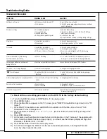
Page 17: ... language Change menu language selection Symbol appears Requested function not available at Certain functions may be disabled during passages this time of a disc Picture is displayed in the wrong Aspect Ratio Incorrect match of Aspect Ratio settings Change Aspect Ratio settings to disc Remote control inoperative Weak batteries Change both batteries Sensor is blocked Clear path to sensor or use rem...

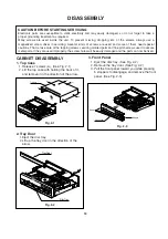
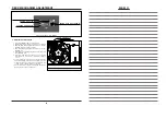
Page 18: ...pitch screws used to secure metal parts If they are used improperly the screw holes will be easily damaged and the parts can not be fixed Top Case A A A A A A A Tray Door Disc Tray Front Panel Stopper Stopper CABINET DISASSEMBLY 1 Top Case 1 Release 7 screws A See Fig 2 1 2 Lift the top case with holding the back of it and remove it in the direction of the arrow Fig 2 1 Fig 2 2 Fig 2 3 3 Front Pan...

Page 19: ... chassis 6 Unscrew 4 screws D at MD Ass y DPM1 7 Turn the portion the direction of arrow to move the Base Assembly Tray in front of you 8 Release the other 3 screws E 9 Disassemble MD Ass y DPM1 from Main chassis 10 Unscrew 4 screws F at Power circuit 11 Disassemble power circuit board from Main chassis CIRCUIT BOARD DISASSEMBLY Note Before removing the main circuit board be sure to shortcircuit t...

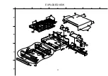
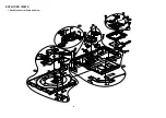
Page 20: ...465 465 250 462 462 300 465 260 465 A46 A47 463 463 275 463 463 463 467 A48 463 463 463 463 463 A00 A43 A43 2 A43 1 283 277 280 285 262 452 452 452 PBTOO DIG901 A 5 4 3 2 1 B C D EXPLODED VIEW 20 ...

Page 21: ...DVM3951NFM PARTS SECTION 250 3110R 0222A CASE TOP DVD 5 H K 275 4811R 0027D BRACKET ASSY MAIN DVM3800 W O GND PVC C 277 4940R V014A KNOB VOLUME HARMANKARDON 280 3721R F176A PANEL ASSY FRONT NORMAL PARTS DVD 50 EVNT 283 3580R T013A DOOR TRAY HARMANKARDON 285 3301R M008A PLATE ASSY SHIELD DVD 50 300 6410RAHS02A POWER CORD AP 10W NI SP2 CORE 80 STP SANG SCREW 452 353 051A SCREW SPECIAL 452 353 051E S...

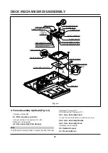
Page 22: ...m Exploded View 016 012 012 014 014 009 013 414 011 008 432 430 430 430 430 031 001 003 004 026 025 002 414 413 413 413 413 413 413 414 414 416 032 034 033 035 416 416 416 416 416 037 038 030 024 022 023 021 020 036 A03 A01 A02 A04 22 ...

Page 23: ...ear Slider Gear Exchange Gear Main Gear Up Down Gear Wheel Main Gear Loading Motor Assembly Main Base Main 3 Screws 2 Connectors 1 Hook 2 Locking Tabs 1 Screw 2 Locking Tabs 2 Screws 1 Connector 2 Screws 1 Screw 2 Screws 5 Connectors 4 Screws 1 Connector 1 Locking Tab 1 Screw 2 Connectors 3 Screws 1 Screw 1 Screw 1 Screw 1 Screw 1 Screw 2 Screws 1 Locking Tab 4 1 4 1 4 1 4 1 4 1 4 2 4 2 4 2 4 2 4 ...

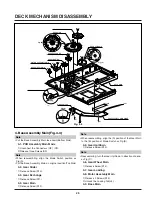
Page 24: ...ocking Tabs L1 located to both sides of the Base Main and then pull the Base Assembly Tray in fornt of you 2 1 Tray Disc Fig 4 2 1 Release Screw S2 Put the Base Assembly Tray face down Bottom side 2 2 Roller Base Tray 1 Unlock the two Locking Tabs L2 2 3 PCB Assembly Tray 1 Release two Screws S3 2 Unconnect the Connector C3 Put the Base Assembly Tray on original position Top Side 2 4 Motor Assembl...

Page 25: ...ASSEMBLY JUNCTION FRAME UP DOWN BASE MAIN FRAME UP DOWN GEAR UP DOWN 3 Frame Assembly Up Down Fig 4 3 1 Release Screw S5 3 1 PCB Assembly Junction 1 Unconnect the 5 Connectors C5 C6 2 Release 2 Screws S6 3 2 Base Assembly Sled Damper Put the Base Assembly Main on original position Top side 1 Release 4 Screws S7 2 Disconnect the Connector C7 3 2 1 Gear Assembly Feed 1 Look the Locking Tab L3 in dir...

Page 26: ...ease three Screws S9 When reassembling align the Mode Switch position as Fig A Put the Base Assembly Main on original position Top Side 4 2 Gear Slider 1 Release Screw S10 4 3 Gear Exchange 1 Release Screw S11 4 4 Gear Main 1 Release Screw S12 When reassembling align the A position of the Gear Main to the B position of Mode Switch as Fig B 4 5 Gear Up Down 1 Release Screw S13 Reassembling turn the...

Page 27: ...erform The S W for Down load at P C 9 Open the Program File for Adjusting Fig 10 10 Click the Down load Icon and perform Program Down load 11 Displayed remaining time 12 Confirm LED No 1 RED and No 2 GREEN is ON 13 Plug out the DVD Set Power cord 14 Disconnect the FFC Cable Fig 1 Printer Cable Fig 2 FFC Cable 15 pin Fig 3 Jig Board Fig 4 Deviation Disc 0 8mm Fig 5 L Wrench 3mm Fig 6 RCA Jack Fig 7...

Page 28: ... SVC 3561 Disc below 30 and TDV 533 Disc below 100 If not Please confirm Play ability on screen You can watch the screen when pressing the Stop key after the Adjusting is finished Then perform Play and Scan Skip operation at Chapter1 and Chapter16 and confirm screen condition normal or abnormal Please obtain these software for Adjusting through our Global Cyber Service Center GCSC Fig 12 Adjusting...

Page 29: ... DPM1 NSP 031 4470R 0069A GEAR SLIDER 032 4470R 0067A GEAR MAIN 033 4470R 0070A GEAR EXCHANGE 034 4470R 0068A GEAR UP DOWN 035 4470R 0071A GEAR LOADING 036 4681R 0012A MOTOR ASSY MAIN 037 4470R 0072A GEAR WHEEL MAIN 038 6871R 3026B PWB PCB ASSY TOTAL DPM1 MAIN MODE SCREW 413 4000R 0006A SCREW TAPTITE 3 8 353 025B 430 1SZZH 1003A SCREW D2 0 6MM SWRCH16A NIY 4 5MM 432 1SZZR 0011A SCREW MACHINE Cabin...

Page 30: ...02 Replace BD101 Bridge rectifier Is R102 100K 2W normal Is about AC 100V app ied to IC101 Pin 5 Check IC101 Is 5 2V applied to IC102 Pin 1 Is there a DC voltage at the terminal of BD101 Check R127 128 SHUTDOWN CKT 1 Power SMPS Circuit No FLD Is 5 2VA section working Replace SMPS trans T101 Replace the inferior components Are F102 D107 D108 and ZD101 open NO NO NO NO NO NO YES YES YES YES YES YES ...

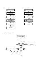
Page 31: ... IC501 Pins 193 808 and 81 normal Do DV 50 Bars appear Do Hello appear at FLD Is P3901 connected normally Is P3901 Pin 8 9 18 normal The waveform on 3 5 7 pin of IC502 normal Check the oscillation Check short OK Replace IC501 or IC306 Check power Refer to power If power is normal OK POWER ON 1 1 YES YES YES YES NO YES YES YES A NO NO NO NO NO NO NO NO YES A ...

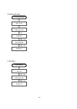
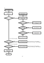
Page 32: ... YES YES If OK YES If OK YES If OK Refer to Audio part Refer to Decoder part Refer to PANTERA part Replace B D Check Front Reconnect it Refer to SERVO part Check the connection of MD AUDIO ABNORMAL OPEN CLOSE ABNORMAL C Video abnormal Check Video jack YES If OK YES If OK YES If OK Refer to Video part Refer to PANTERA part Replace B D VIDEO ABNORMAL ...

Page 33: ...re abnormal Check the disc If OK YES If OK YES If OK Refer to Servo part Check DSP Check PANTERA Replace B D PICTURE ABNORMAL F Disc Error Check Disc YES If OK YES If OK Refer to Servo part Replace B D DISC ERROR ...

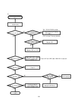
Page 34: ... the audio sound output from PANTERA decoder Does the moving picture of the video CD play on the screen normally Does the audio sound output normally END Check power clock Check CD DVD DSP output signal Check CD DVD DSP output signal Check CD DVD DSP output signal Check clock signal Check clock signal YES YES YES YES YES YES YES YES YES YES NO NO NO OK NO NO NO NO NO 3 PANTERA Circuit _ OPTION _ I...

Page 35: ...of IC901 Pin 22 Does pulse waveform of RC901 Pin 1 appear Is IC901 Pin 17 connected to RC901 Pin 1 Is RC901 Pin 2 5V Power on Check and replace R916 R926 R925 Solder defective parts again Solder defective parts Replace IC901 Solder Key part Check Power Replace IC902 Replace IC901 Replace LED9A1 Replace RC901 Re solder Recheck Replace IC901 Complete repairing Front B D NO NO NO NO NO NO NO NO NO YE...

Page 36: ...TTL pulse output to IC201 Pins 140 142 Does 33 8688MHz clock input to IC201 Pin 63 Is IC201 Pins 83 84 88 89 voltage about 2 2V Replace IC201 IC206 soldering or IC defect Check power circuit Check 2 PANTERA Part Replace X201 or IC206 30MHz clock defect CHECK POINT General 5 RF Servo Circuit A END NO NO NO NO NO YES YES YES YES YES ...

Page 37: ...e up and down Check Focus Driver output IC201 Pin 83 IC2M1 Pins 37 38 Check SLED Driver output IC201 Pin 88 IC2M1 Pins 28 29 IC201 Pin 88 no output IC201 is defective IC2M1 Pins 28 29 no output IC2M1 is defective IC201 Pin 83 no output IC201 is defective IC2M1 Pins 37 38 no output IC2M1 is defective DECK assembly is defective Slide the pick up to inner track Power on Check loading Part Push Pick u...

Page 38: ...ear OPEN CLOSE Replace IC501 or IC201 Replace IC201 Check IC2A1 Pin 11 12 13 14 in DVD Mode Fig 3 FOCUS ERROR waveform IC201 no output Pick up is defective Check IC201 and IC2M1 when PMD03 Pin 5 is abnormal Check IC2M1 Pin 21 PMD03 Pin 5 turn when the IC2M1 Pin 21 is less than 2 2V Check A Video Part is defective Check PANTERA Circuit Check 7 OSD Video Circuit Replace PANTERA part IC2A1 is defecti...

Page 39: ...RF 1 5 1 6V IC2A1 Pin 57 Fig 5 RF waveform Check IC2A1 Pins 5 6 7 8 No signal Pick up is defective Replace IC201 Check IC201 Pin84 No signal at IC201 IC201 is defective Check IC201 Pin 162 Check the clock at the IC201 Pins 28 30 Both are normal IC201 is defective Replace IC2A1 CHECK A D END NO NO NO NO YES YES YES YES ...

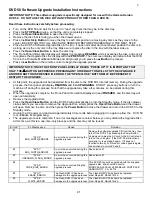
Page 40: ...lso allow the user to compensate for errors in the disc authoring Harman Kardon AVR receiver s multi remote command will no longer interfere with the DVD 50 Control system has been improved to prevent the unit from locking up when certain combinations of buttons are pressed just prior to turning the DVD50 off Revised decoding and processing for improved overall audio and video performance Video mo...

Page 41: ...f during this process Note that the upgrade may take a few minutes so be patient during this process When the upgrade is complete the Front Panel Information Display will read FINISHED and the disc tray will open automatically Remove the Upgrade Disc Press the Open Close Button and the DVD 50 will automatically go into the Standby mode If the disc drawer closes before you are able to remove the Up...

Page 42: ...e disc into play Press and hold the Check Button on the remote for two to three seconds until a message appears in the upper left corner of the screen reading MODE 2 To change to a different mode wait until the MODE message disappears and then immediately press and hold the Check Button for three seconds The next mode will take effect when you see another MODE indication message We suggest that yo...

Page 43: ...ctors PMD02 PMD03 on the Main PCB 7 Lift and remove entire support bracket with Main and Output PCB s attached and set it outside the unit 8 Remove three Phillips screws holding the plastic clamp lift and remove clamp 9 Remove the single Phillips screw in the middle of the 5 tray disc Lift and remove the disc it must be manipulated to clear two plastic tabs at the rear of the tray base 10 Detach t...

Page 44: ...44 2 Service bulletin H K2002 02 March 2002 Subject Faulty 23 Pin Flat Cable ...

Page 45: ...NSE LOCK E_SOUT ZISENB XRST DAC_RST 16 9 PAL_SW AUTO_SW MIC_ON Y_SEL A_MUTE DAC_CS1 DAC_CS2 V_MUTE DAC_CLK DAC_OUT ADCCLK ACT_MUTE LOAD_OPEN LOAD_CLOSE MIRR AD 00 19 PSENB FLD FLD_CS FLD_CLK FLD_OUT FLD_CS FLD_CLK FLD_OUT CPLD EE_CS EE_CLK EE _OUT F_IN IC3F1 FLASH ROM F_IN MRESET 74573 FLASH_CS RD PWEO LA0 LA1 LA2 LA3 ALE AD 04 19 LADD 04 19 MD 00 31 MCLK2 CKE MA 00 10 MA12 13 CS0 RAS CAS WE DQM0 ...

Page 46: ... ER L I NE FI L TER SWI TCHI NG TR TRANS FEED B REG 8V 8V 5 2VA VF RECTIFIER FLD RECTIFIER 9V RECTIFIER 5 2V LPF LPF RECTIFIER 14V LPF 12VA AC120V PWR ON OFF REG 3 3V REG 3 3V 2 5V 3 3V 3 3V_M 12VA 2 Power SMPS Block Diagram 46 ...

Page 47: ...I F focus tracking loading sled Spindle M D PICK UP MCK IC206 DVDSP 3301 CD DVD DSP DVD SERVO IC2A1 33P3721 RF Signal Processor FDO TDO FMO Load open close loading control UCOM I F DVD A B C D FE TE PI SBADD 4 4 DVD CD RF DRAM 256K x 16bit 16 9 ICADDR 0 8 ICDATA 00 15 DO 0 7 AO 0 5 DVD_DATA 0 7 MON MDP SPINDLE_FG MPEG I F 2 2 DSP_CS WR RD 3 3 8 8 3 RF CD DSP DVD DSP DVD SERVO Block Diagram 47 ...

Page 48: ...IC401 WM8716 Audio DAC IC402 LPF Buffer NJM4580D OP AMP DAC_RST S_DATA S_CLK DAC_L0 DA_LRCK DA_DATA0 DA_BCK DA_XCK L R U COM I F L R MPEG I F 4 AUDIO Block Diagram 48 ...

Page 49: ... SQS0 REQP SDCLK1 PSYNC DSP_INT SENSE DSP_CS AD 00 19 RF MOTOR I F MIRR LDON SCLK SDATA EE_CS F_IN 32 MD 00 31 MCLK2 CKE MA 00 10 MA12 13 CS0 RAS CAS WE DQM 0 3 SPINDLE_FG ALE AD 04 19 16 LADD 04 19 16 LA 0 3 4 AD 00 15 16 AUDIO I F DA_DATA DA_BCK DA_LRCK DA_XCK DAC_L0 DAC_L1 DAC_RST A V JACK I F C R B CVBS G R Y B G CVBS V_MUTE 16 9 ZISENB RD PWED 5 MPEG MEMORY Block Diagram 49 ...

Page 50: ...ch Ch1 Ch3 500mV T T 3 IC501 Pin 114 Luminance Super video out Mode Tek Stop 1 00kS s 3290 Acqs M 500µs CH1 280 mV Edge Slope Type Edge Source Ch1 Coupling DC Level 280mV Mode Holdoff 3 Ch3 1 00V T T Slope T IC501 Pin 99 PANTER MAIN IC501 Pin 112 Component Pb IC501 Pin 110 Component Pr TURN from Motor Drive Reverse turn Sensor 1 disc position Sensor 2 disc ready TURN Signal from µ com TE TZC After...

Page 51: ...N NO 164 165 166 167 168 169 170 171 172 173 174 175 176 177 178 179 180 181 182 183 184 185 186 187 188 189 190 191 192 193 194 195 196 197 198 199 200 201 202 203 204 205 206 207 208 209 210 211 212 213 214 215 216 217 218 3 1 3 1 3 1 3 1 3 1 3 1 3 1 0 3 1 3 1 3 1 1 5 3 1 0 3 1 3 1 3 1 3 1 3 18 0 086 3 2 4 2 3 0 0 3 1 0 0 017 2 2 3 1 3 1 0 3 18 1 3 3 1 3 1 3 1 0 2 3 3 1 0 001 3 1 3 1 3 1 1 6 3 1...

Page 52: ...52 ...

Page 53: ...53 ...

Page 54: ...54 ...

Page 55: ...55 ...

Page 56: ...56 ...

Page 57: ...942 CAPACITOR CHIP CERAMIC M L HD 0 1UF 50V Z Y5V F 1508 R TP C210 0CH1104K942 CAPACITOR CHIP CERAMIC M L HD 0 1UF 50V Z Y5V F 1508 R TP C221 0CH8476C611 CAPACITOR CHIP AL ELECTROLYTI 47UF 6 3V M 85STD CYL R TP C223 0CH1104K942 CAPACITOR CHIP CERAMIC M L HD 0 1UF 50V Z Y5V F 1508 R TP C224 0CH1104K942 CAPACITOR CHIP CERAMIC M L HD 0 1UF 50V Z Y5V F 1508 R TP C226 0CH1104K942 CAPACITOR CHIP CERAMIC...

Page 58: ...TROLYTI 47UF 6 3V M 85STD CYL R TP C2D4 0CH8476C611 CAPACITOR CHIP AL ELECTROLYTI 47UF 6 3V M 85STD CYL R TP C2D5 0CH1225F944 CAPACITOR FIXED CERAMIC Temp c 2 2UF 16V 80 20 Y5V F 3216 C2D6 0CH1104K942 CAPACITOR CHIP CERAMIC M L HD 0 1UF 50V Z Y5V F 1508 R TP C2D7 0CH1104K942 CAPACITOR CHIP CERAMIC M L HD 0 1UF 50V Z Y5V F 1508 R TP C2E1 0CH1182K562 CAPACITOR CHIP CERAMIC M L HD 1800P 50V K X7R 1 6...

Page 59: ...F 16V M 85STD CYL R TP C492 0CH1104K942 CAPACITOR CHIP CERAMIC M L HD 0 1UF 50V Z Y5V F 1508 R TP C493 0CH1104K942 CAPACITOR CHIP CERAMIC M L HD 0 1UF 50V Z Y5V F 1508 R TP C503 0CH1104K942 CAPACITOR CHIP CERAMIC M L HD 0 1UF 50V Z Y5V F 1508 R TP C504 0CH7106C611 CAPACITOR FIXED TANTALUM 10UF 6 3V 20 3216 TP C506 0CH7106C611 CAPACITOR FIXED TANTALUM 10UF 6 3V 20 3216 TP C508 0CH1104K942 CAPACITOR...

Page 60: ...L D113 0DR154020BA DIODE RECTIFIER 1N5402 BK GULF SEMICONDUCTOR L D114 0DR104009AB DIODE RECTIFIER RL104 R TP GULF SEMICONDUCTOR D116 0DR104009AB DIODE RECTIFIER RL104 R TP GULF SEMICONDUCTOR D2A1 0DS202009CA DIODE SWITCHING DAN202K TP ROHM KOREA SOT23 80 D2A2 0DS202009CA DIODE SWITCHING DAN202K TP ROHM KOREA SOT23 80 DIGITRON DIG901 6302R V111A DIGITRON 14 BT 64GNK FUTABA UNIVERSAL FUSE FH101 586...

Page 61: ... EMI HB 1M2012 102JT CERATECH TP 3K L207 6200HJC102A FILTER CIRC EMI HB 1M2012 102JT CERATECH TP 3K L208 6200HJC102A FILTER CIRC EMI HB 1M2012 102JT CERATECH TP 3K L211 6200HJC102A FILTER CIRC EMI HB 1M2012 102JT CERATECH TP 3K L2A1 6200HJC102A FILTER CIRC EMI HB 1M2012 102JT CERATECH TP 3K L2A2 6200HJC102A FILTER CIRC EMI HB 1M2012 102JT CERATECH TP 3K L2A3 6200HJC102A FILTER CIRC EMI HB 1M2012 1...

Page 62: ...E Q403 0TR387509AC TRANSISTOR CHIP KTC3875S GR T1 ALG KEC Q404 0TR100009BM TRANSISTOR UMZ1N TL UM6 3K TP ROHM Q406 0TR387509AC TRANSISTOR CHIP KTC3875S GR T1 ALG KEC Q407 0TR387509AC TRANSISTOR CHIP KTC3875S GR T1 ALG KEC Q408 0TR387509AC TRANSISTOR CHIP KTC3875S GR T1 ALG KEC Q409 0TR387509AC TRANSISTOR CHIP KTC3875S GR T1 ALG KEC Q410 0TR387509AC TRANSISTOR CHIP KTC3875S GR T1 ALG KEC Q601 0TR12...

Page 63: ... OHM 1 16 W 1608 5 00 D R296 0RH1500C622 RESISTOR METAL GLAZED CHIP 150 OHM 1 16 W 1608 5 00 D R297 0RH1201C622 RESISTOR METAL GLAZED CHIP 1 2K OHM 1 16 W 1608 5 00 D R2A0 0RH1002C622 RESISTOR METAL GLAZED CHIP 10K OHM 1 16 W 1608 5 00 D R2A1 0RH0912C622 RESISTOR METAL GLAZED CHIP 91 OHM 1 16 W 1608 5 00 D R2A2 0RH1202C622 RESISTOR METAL GLAZED CHIP 12K OHM 1 16 W 1608 5 00 D R2A4 0RH0000C622 RESI...

Page 64: ...P 4 7K OHM 1 16 W 1608 5 00 D R306 0RH4701C622 RESISTOR METAL GLAZED CHIP 4 7K OHM 1 16 W 1608 5 00 D R307 0RH5600C622 RESISTOR METAL GLAZED CHIP 560 OHM 1 16 W 1608 5 00 D R308 0RH5600C622 RESISTOR METAL GLAZED CHIP 560 OHM 1 16 W 1608 5 00 D R309 0RH1002C622 RESISTOR METAL GLAZED CHIP 10K OHM 1 16 W 1608 5 00 D R310 0RH5600C622 RESISTOR METAL GLAZED CHIP 560 OHM 1 16 W 1608 5 00 D R311 0RH5600C6...

Page 65: ...L GLAZED CHIP 330 OHM 1 16 W 1608 5 00 D R428 0RH2200C622 RESISTOR METAL GLAZED CHIP 220 OHM 1 16 W 1608 5 00 D R429 0RH0752C622 RESISTOR METAL GLAZED CHIP 75 OHM 1 16 W 1608 5 00 D R430 0RH1002C622 RESISTOR METAL GLAZED CHIP 10K OHM 1 16 W 1608 5 00 D R431 0RH2201C622 RESISTOR METAL GLAZED CHIP 2 2K OHM 1 16 W 1608 5 00 D R432 0RH1001C622 RESISTOR METAL GLAZED CHIP 1K OHM 1 16 W 1608 5 00 D R434 ...

Page 66: ...N FILM 820 OHM 1 6 W 5 00 TA26 R916 0RD6800F608 RESISTOR FIXED CARBON FILM 680 OHM 1 6 W 5 00 TA26 R917 0RD1501F608 RESISTOR FIXED CARBON FILM 1 5K OHM 1 6 W 5 00 TA26 R918 0RD1201F608 RESISTOR FIXED CARBON FILM 1 2K OHM 1 6 W 5 00 TA26 R919 0RD8200F608 RESISTOR FIXED CARBON FILM 820 OHM 1 6 W 5 00 TA26 R920 0RD6800F608 RESISTOR FIXED CARBON FILM 680 OHM 1 6 W 5 00 TA26 R925 0RD1002F608 RESISTOR F...

Page 67: ...H KONY CHIP 27MHZ 20P X5A1 6212R K001A RESONATOR CSTCC10M0G53 R0 MURATA 10MHZ R X901 6202R BJ01A CRYSTAL STANDARD HC 49 S SUNNY RADIAL 5 0000MHZ ZD101 0DZ560009CA DIODE ZENER MTZ5 6B TP ROHM K ZD601 0DZ562609BA DIODE ZENER GDZJ5 6C 26MM TP GRANDE DO34 ZD602 0DZ562609BA DIODE ZENER GDZJ5 6C 26MM TP GRANDE DO34 ZD603 0DZ562609BA DIODE ZENER GDZJ5 6C 26MM TP GRANDE DO34 ZD604 0DZ562609BA DIODE ZENER ...

Page 68: ...CIRCUIT DIAGRAM 1 POWER SMPS CIRCUIT DIAGRAM NOTE 1 Shaded parts are critical for safety Replace only with specified part number 2 Voltages are DC measured with a digital voltmeter during Play mode Oscillation abnormal Digitron no Power 12V line dead 3 3V line dead No Power 8V line dead 5V_A 5V_D No Power No Power 68 ...

Page 69: ... audio abnormal MPEG Interface Line µ com Interface Data µ com Interface adress CD DVD picture audio abnormal Tracking Focus Servo fail Tracking Servo fail Spindle Motor abnormal CD DVD picture audio abnormal Focus Servo fail Tracking Servo fail Scratched Disc abnormal Sled Servo fail DRAM Control Disc Detect Error Spindle Servo fail 69 ...

Page 70: ...ervo Loop WAVEFORM Turntable not operate Tray Loading Speed control Turn table speed control Spindle Motor unstable Actuator spindle sled not operate DVD laser not operate CD laser not operate Servo fail DVD Mode fail DVD Laser not operate Tracking Servo fail Focus Servo fail µ com Interface line CD DVD picture abnormal ...

Page 71: ...b Pr Component Y c S VHS Audio L R OUT CVBS 3 4 PANTERA CIRCUIT DIAGRAM No Power on Audiuo DAC Interface System not operate CD Text not working or CD not Loading DSP interface line Spindle Motor unstable System not working or Digitron not display 71 ...

Page 72: ...ot memoried setup Menu Turntable not operating No Disc display Tray not open close Tray not closed Pick up not initial operating Disc Detec Error Disc number detect error Digitron all not display and system not operate Digitron all not display System not working Digitron all not display System not working 72 ...

Page 73: ...9 6 TIMER KEY CIRCUIT DIAGRAM System not operate System not operate Remocon not operate Power not control Digitron abnormal Digitron abnormal 73 ...

Page 74: ... Component Y c S VHS Audio L R OUT CVBS Super jack output Video line not output Video line not output Video line not mute Audio line not output Audio not output Audio output bad Optical Coaxial Audio bad TV Composite RGB Mode not changed Automatically 74 ...

Page 75: ...nent Y c S VHS Audio L R OUT CVBS SCART JACK MODEL ONLY Super Jack Output Y Pb Pr output for NTSC TV Composit R G B Mode not changed Automatically Audio not output Audio popnoise occur Video not output or video abnormal 16 9 can t be change R G B output for PAL 75 ...

Page 76: ...ts List Ref Part Number Description 801 3835RS0016K DVD50 OWNER S MANUAL USA 802 3890R H907M DVD50 OUTER CARTON 120V 803 3920R E018A STYRO END PADS 2 804 PACKING SHEET 806 17 1355 DVD50 S VIDEO CABLE 808 1 5V AA BATTERY FOR RC PAIR 810 861 520G CABLE ASSEMBLY SET 811 564 017B PLUG ASSY PHONO CORD 1WAY YL 812 564 018B PLUG ASSY PHONO CORD 2WAY RD WH 900 6711R1Z017D DVD50 REMOTE CONTROL ...

Reviews: