background image

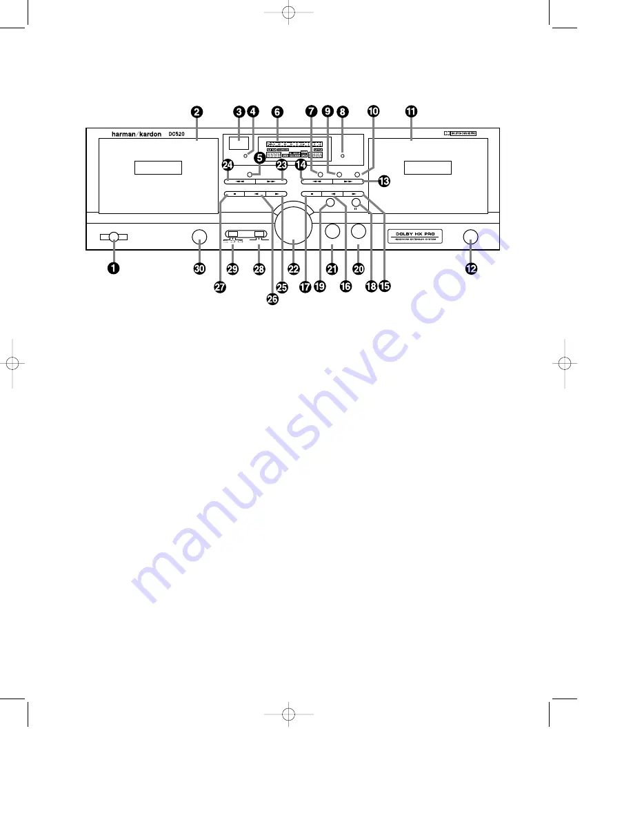
Front Panel Controls

A

Power Switch 

– Press this

switch once to turn it on. Press it
again to turn the unit off. An indica-
tor around the switch turns green
when the unit is turned on.

B

Secondary Transport 

– This

is the secondary, playback only,
transport. Use it for tapes that will be
the source material during dubbing
operation.

C

Remote Sensor

– The remote

sensor behind this area is compati-
ble with the commands from many
Harman Kardon remote controls.
Keep this area clear if you wish to
use the DC520 with a remote control.
(not included)

D

Secondary Counter Reset 

Press this button to reset the counter
for the secondary transport to “0000”

E

Sync Reverse 

– This button

activates circuitry that compensates
for record and playback tapes of
unequal length.

F

Information Display 

– This

display provides detail about the
operation of the DC520. See the
separate explanation of each indica-
tor on page 4.

G

Copy Button

– Press this button

to activate normal speed dubbing

H

Primary Counter Reset 

Press this button to reset the counter
for the primary transport to “0000”.

I

High Speed Copy 

– Press this

button to activate high speed dub-
bing.

J

Record Mute

– Press this button

during recording to momentarily mute
the input and insert blank space.

K

Primary Transport 

– Insert

tapes here for recording or play-
back. This transport should always
contain the record tape during dub-
bing.

L

Primary Transport Eject 

Press this button to open the primary
transport door.

M

Primary Transport Fast

Forward 

– Press this button to

rapidly advance the primary tape.

N

Primary Transport Rewind 

Press this button to rewind the pri-
mary tape.

O

Primary Transport Forward

Play 

– Press this button to play the

primary tape.

P

Primary Transport Reverse

Play 

– Press this button to play the

primary tape in a reverse direction.

Q

Primary Transport Stop 

Press this button to stop the primary
transport.

R

Pause 

– Press this button to

pause the transport in use.

S

Record

– Press this button to

place the unit in the record ready
mode. Press it simultaneously with a
play button

OP

to start a recording.

3

DC520 – 8•16•96  ver (D)

T

Headphone Jack 

– Insert

stereo headphones here for private
listening or record monitoring.

U

Input Balance 

– This control

adjusts the left/right record balance.

V

Input Level

– This knob controls

the input level during recordings.

W

Secondary Transport 

Fast Forward 

– Press this button

to rapidly advance the secondary
tape.

X

Secondary Transport

Rewind 

– Press this button to

rewind the secondary tape.

Y

Secondary Transport

Forward Play 

– Press this button

to play the secondary tape.

Z

Secondary Transport

Reverse Play 

– Press this button

to play the secondary tape in a
reverse direction.

a

Secondary Transport Stop 

Press this button to stop the sec-
ondary transport.

b

Dolby NR Selector 

– This

switch selects which type of Dolby
Noise Reduction, if any, is in use.

c

Direction Mode Selector 

This switch selects the playback/auto
reverse mode for the tape in use.

d

Secondary Transport Eject

Press this button to open the 
secondary transport door.

SECONDARY Transport

Auto Tape Selector

Power

Eject

Eject

Input Balance

Headphones

Direction Mode

Cont Play

Off

B

C

Dolby NR

Input Level

Dual  Auto Reverse

Reset

Sync Rev

PLAY

PRIMARY Transport

Auto Tape Selector

Dual  Auto Reverse

REC/PLAY

Reset

Copy

Record

High Speed Copy Rec Mute

 •DC520 (d).qx  11/6/96 12:02  Page 6

Summary of Contents for DC520

Page 1: ... Part 1111 DC520 SECONDARY Transport Auto Tape Selector Power Eject Direction Mode Cont Play Off B C Dolby NR Input L Dual Auto Reverse Reset Sync Rev PLAY DC520 8 16 96 ver D Back Cover DC520 d qx 11 6 96 12 02 Page 1 ...

Page 2: ...Dolby NR Input Level Reset Sync Rev PRIMARY Transport Auto Tape Selector Dual Auto Reverse REC PLAY Reset Copy Record HighSpeedCopy Rec Mute Harman Kardon DC520 Dual Cassette Deck Owner s Manual DC520 8 16 96 ver D Front Cover DC520 d qx 11 6 96 12 02 Page 2 ...

Page 3: ...IRE LA LAME LA PLUS LARGE DE LA FICHE DANS LA BORNE CORRESPONDANTE DE LA PRISE ET POUSSER JUSQU AU FOND The lightning flash with arrowhead symbol within an equalateral triangle is intended to alert the user to the presence of uninsulated dangerous voltage within the product s enclosure that may be of sufficient magnitude to consittute a risk of electric shock to persons The exclamation point withi...

Page 4: ...power cords under rugs or carpets or place heavy objects on them Damaged power cords should be replaced immediately with cords meeting factory specifications Handle the AC Power Cord Gently When disconnecting the power cord from an AC outlet always pull the plug never pull the cord If you do not intend to use the unit for any considerable length of time disconnect the plug from the AC outlet Do No...

Page 5: ...used to protect your new DC520 during ship ment were specially designed to cushion it from shock and vibration We suggest that you save the carton and packing materials for use in shipping if you move or should the unit ever need repair To minimize the size of the carton in storage you may wish to flatten it This is done by carefully slitting the tape seams on the bottom and collapsing the carton ...

Page 6: ...d Press this button to rewind the pri mary tape O Primary Transport Forward Play Press this button to play the primary tape P Primary Transport Reverse Play Press this button to play the primary tape in a reverse direction Q Primary Transport Stop Press this button to stop the primary transport R Pause Press this button to pause the transport in use S Record Press this button to place the unit in ...

Page 7: ...nect the INPUT jacks on the DC520 to the TAPE OUTPUT jacks of your receiver or pre amp Connect the power to a non switched AC wall output or to the accessory outlet on the rear of another audio device in your system and you are ready to go NOTE When using the accessory outlet on another product to power the DC520 make certain that it has the ability to power a device that draws at least 14 watts o...

Page 8: ...ecessary internal adjustments No switch settings are required to indi cate the tape type Once a tape has been inserted follow these steps to make a recording 1 Select the type of Dolby Noise Reduction desired if any using the DOLBY NR switch b 2 Press the RECORD button S to place the unit in the Record Ready mode and observe that the LEVEL METER 1 will begin to react to the incoming audio source A...

Page 9: ...Any of the Auto Reverse modes may be stopped at any time by pressing the STOP button Qa Counter Operation Each transport has a separate tape counter 3 that indicates the motion of the transport and the relative amount of tape used When in the normal or fast forward mode the numbers will increase When the unit is in a reverse mode the numbers will decrease To reset either counter press the appro pr...

Page 10: ... REV indicator 4 will illuminate 4 Press either the Copy G or High Speed Copy I button to start the dub process The tapes will follow one of the two fol lowing modes depending on the rela tionship of the length of the original tape to the copy tape If the original tape in the Secondary Transport for playback is shorter than the record tape in the Primary Transport the dub will start by record ing ...

Page 11: ...eld AC powered demagnetizers are more effective as they generate stronger fields Consult your dealer for information on this type of unit and be certain to follow the instructions carefully When using this type of unit be certain to keep it away from prerecorded tapes when it is turned on as it may erase them Care of Tapes 1 Store cassettes in their cases in a loca tion away from direct sunlight e...

Page 12: ...in wrong transport Input level too high Mismatched Dolby NR modes Tape is worn Mismatched Dolby NR modes Tape heads are dirty Tape heads have become magnetized SOLUTION Make certain AC power cord is firmly plugged into a live outlet Check to see if outlet is switch controlled Check to see if level indicators do not move This confirms a blank tape Check switch settings at receiver Make certain that...

Reviews: