background image

●  

System Setup

Once the speakers have been placed in the
room and connected, the remaining steps in
the setup process are to program the AVR 500’s
bass management system for the type of
speakers used in your system, calibrate the
output levels, and set the delay times used by
the surround sound processor.

You are now ready to power up the AVR 500 to
begin these final adjustments.

1. Plug the 

Power Cable

°

into an

unswitched AC outlet.

2. Press the 

Main Power Switch

1

in so

that it latches in with the word “OFF”
appearing on the top of the switch inside
the front panel. Note that the 

Power

Indicator

will turn amber, indicating

that the unit is in the Standby mode.

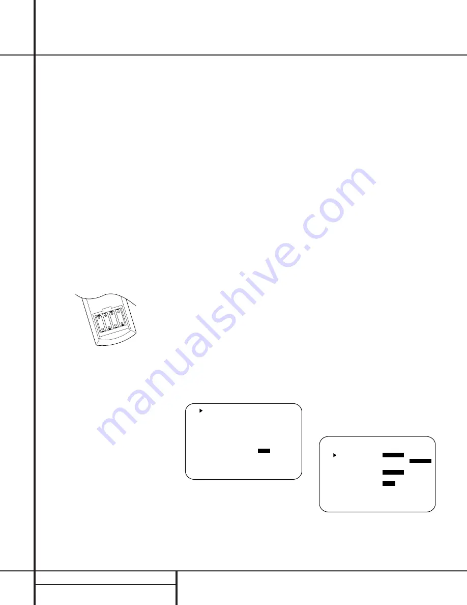
3. Install the four supplied AAA batteries in

the remote as shown. Be certain to follow
the (+) and (–) polarity indicators that are
on the bottom of the battery compartment.

4. Turn the AVR 500 on either by pressing the

System Power Control

2

on the front

panel, or via the remote by first pressing the

AVR Selector

a

or any of the CD/Tape/

DVD selectors 

b

on the remote. The 

Power

Indicator 

3

will turn green to confirm that

the unit is on, and the 

Information Display

35  

will also light up.

Using the On-Screen Display

When making the following adjustments, you
may find them easier to make if you use the
unit’s on-screen display system. These easy-to-
read displays give you a clear picture of the cur-
rent status of the unit and make it easy to see
which speaker, delay, input or digital selection
you are making.

To view the on-screen displays, make certain
you have made a connection from the 

TV

Monitor Video Out 

jack 

b

on the rear panel

to the composite or S-Video input of your TV or
projector. In order to view the AVR’s displays,
the correct video source must be selected on
the video display.

IMPORTANT NOTE:

When viewing the displays

on a projection TV it is important that they not be
left on the screen for an extended period of time.
As with any video display, but particularly with
projectors, constant display of a static image such
as these menus or video- game images may
cause the image to be permanently “burned
into” the CRT. This type of damage is not covered
by the AVR 500 warranty and may not be cov-
ered by the projector TV set’s warranty.

The AVR 500 has two on-screen display modes,
“Semi-OSD” and “Full-OSD.” When making
configuration adjustments, it is recommended
that the Full-OSD mode be used. This will place
a complete status report or option listing on
the screen, making it easier to view the avail-
able options. The Semi-OSD mode uses one-line
displays only.

To view the Full-OSD screens, press the OSD
button 

s

three times. The first press will bring

up the Semi-OSD mode and the second press
will turn the OSD system off; the third press will
call up the Full-OSD display (Figure 1).

When either OSD mode has been selected, a
message will appear at the bottom of the
screen any time the mode or source is changed.
First, the new mode or source will show, and if
the source is changed there will also be a con-
firmation of the mode in use.

Note that the full-screen displays will time-out
after 20 seconds. However, the on-screen display
used with the channel output level adjustments
will remain on the screen as long as the settings
are being changed. This display must be manu-
ally turned off by pressing the OSD button 

·

.

Figure 1

When making most setup adjustments, the full
on-screen readout may be displayed at any
time by pressing the 

OSD

button 

s

once.

The displays will remain on the screen as long
as adjustments are being made, or for twenty
seconds after the last button is pressed to
change a setting.

Speaker Configuration

The first few adjustments tell the AVR 500
which type of speakers are in use. This is
important as it adjusts the settings that deter-
mine which speakers receive low-frequency
(bass) information. For each of these settings
use the 

LARGE

setting if the speakers for a

particular position are traditional full-range
loudspeakers that are capable of reproducing
sounds below 100Hz. Use the 

SMALL

set-

ting for smaller, frequency-limited satellite
speakers that do not reproduce sounds below
100Hz. Note that when “small” speakers are
used, a subwoofer is required to reproduce
low-frequency sounds. Remember that the
“large” and “small” descriptions do not refer
to the actual physical size of the speakers, but
their ability to reproduce low-frequency
sounds. If you are in doubt as to which cat-
egory describes your speakers, consult the
specifications in the speakers’ owner’s manual,
or ask your dealer.

With the AVR 500 turned on, follow these steps
to configure the speakers:

1. Put the AVR 500 in the Dolby Pro Logic

mode by pressing the 

Dolby Pro Logic

Selector

Ó

on the front panel or by

pressing the 

Surround Mode Selector

31

on the remote, followed by the

/

¤

buttons 

g

until 

PRO LOGIC

appears

in the 

Main Information Display

V

and

the 

PRO LOGIC

indicator 

G

lights.

2. Press the 

Speaker

button 

k

33 

on the

remote or front panel. The words 

FRNT

SPEAKER

will appear in the 

Main

Information Display

V

.

If you are using the on-screen display sys-
tem, a display will appear indicating the
status of each speaker (Figure 2).

Figure 2

3. Press the 

Set

button 

i 31  

and note

that the 

pointer will stop flashing.

      M O D E   : D O L B Y   P R O   L O G I C


      F R O N T   S P   :

L A R G E

  S M A L L

      C E N T E R   S P : L A R G E  

S M A L L

                          N O N E

      S U R R   S P K   :

L A R G E  

S M A L L

                          N O N E

      S U B W O O F E R :

O F F  

O N


      M A S T E R   V O L U M E : Ð 2 0 D B

      A U D I O   S O U R C E   : D I G I T A L

      V I D E O   S O U R C E   : D V D

      A U D I O   I N P U T     : O P T   1  

      B I T S T R E A M   I N   : 3 / 2 . 1 C H  

      S U R R .   M O D E   : D O L B Y

    D I G I T A L

 M U L T I   R O O M   :

O F F  

O N

      M A S T E R   V O L U M E : Ð 2 0 D B

16

SYSTEM CONFIGURATION

System Configuration

Summary of Contents for AVR 500

Page 1: ...250 Crossways Park Drive Woodbury New York 11797 www harmankardon com 1999 Harman Kardon Incorporated Printed in China Part 1111 AVR500OM 6311 004 010 ...

Page 2: ...ID 2 VID 3 6 CH AM FM PRESET SCAN TUN MODE VMAx LOGIC 7 C M THEATER SURR OFF PRESET TUNING Phones Power R L Max Min Max Min Bass Treble Balance Volum Speaker Multi Room Dig Select Delay DIGITAL PRO LOGIC 3 STEREO Set VI Video DIGITAL COAX Power for the digital revolution ...

Page 3: ...es TV 34 Setup Code Tables VCR 36 Setup Code Tables CD 36 Setup Code Tables DVD 37 Setup Code Tables DVD LD 37 Setup Code Tables CABLE 37 Setup Code Tables SAT 38 Troubleshooting Guide 38 Processor Reset 39 Technical Specifications AVR 500 Audio VideoReceiver Typographical Conventions In order to help you use this manual with the remote control front panel controls and rear panel connections certa...

Page 4: ...eld environments and more defined pans and flyovers Our exclusive VMAx delivers a spacious sound field even when only two front speakers are available A total of four audio video inputs each with both composite and S Video as well as three additional audio only inputs are selected through a learning remote control and an easy to read front panel display or on screen graph ics through a TV monitor ...

Page 5: ...nstallation in extremely hot or cold locations or an area that is exposed to direct sunlight or heating equipment Avoid moist or humid locations Do not obstruct the ventilation slots on the top of the unit or place objects directly over them Cleaning When the unit gets dirty wipe it with a clean soft dry cloth If necessary wipe it with a soft cloth dampened with mild soapy water then a fresh cloth...

Page 6: ... channels by as much as 10dB Set this control to a suitable position for your taste or room acoustics 6 Treble Control Turn this control to modify the high frequency output of the left right chan nels by as much as 10dB Set this control to a suitable position for your taste or room acoustics 7 Balance Control Turn this control to change the relative volume for the front left right channels NOTE Fo...

Page 7: ...g to an analog program that is encoded with surround sound informa tion See page 21 23 for more information on surround modes Ô Dolby 3 Stereo Selector Press this but ton to select the Dolby 3 Stereo listening mode This mode is used primarily when a center channel speaker but no surround speakers are installed See pages 22 for more information on surround modes VMAx Mode Selector Press this button...

Page 8: ...appears for the Music version of Logic 7 K DTS Mode Indicator This indicator illumi nates when a DTS encoded source is playing L Surround Off This indicator illuminates when the surround processing has been dis abled by pressing the Surround Off button Ù When this indicator is lit the AVR 500 will play traditional stereo sound using the front left and front right speakers only M Multiroom System I...

Page 9: ... 8 Ohms SPEAKER 8 Ohm LEFT CENTER FRONT CENTER a a b f g fl fi VIDEO 1 DIGITAL INPUT c e d ª Video 1 Inputs Video 1 Outputs AM Antenna FM Antenna DVD Inputs 6 Channel Direct Inputs CD Inputs Multiroom Audio Outputs ª Digital Outputs Preamp Outputs Subwoofer Output Multiroom IR Input Front Speaker Terminals Center Speaker Terminals fi Surround Speaker Terminals fl Switched AC Outlet Unswitched AC O...

Page 10: ... be certain to maintain correct polarity between the speak er s terminals and those on the AVR by con necting red termianls to red and black terminals to black See page 13 for more infor mation on speaker polarity fl Switched AC Outlet This outlet may be used to power any device that you wish to have turn on when the unit is turned on with the System Power Control switch 2 Unswitched AC Outlet Thi...

Page 11: ...lect l 6 Ch Direct Input m Video Input Selectors n AM FM Tuner Select o Tuner Mode p Memory Button q Numeric Keys r Macro 1 2 Buttons s OSD Button t Light Button u Direct Macro Button v Clear Macro Button w Preset Up Down x Tuning Up Down y Forward Reverse Transport Buttons z Night Mode Multi Room 28 Delay Prev Ch 29 Button 30 Speaker Select 31 Surround Mode Selector 32 Volume Up Down 33 Sleep But...

Page 12: ...ttons are also used to increase or decrease output levels when configuring the unit with either the inter nal test tone or an external source They are also used to enter delay time settings after the Delay button 28 has been pressed h Channel Select Button This button is used to start the process of setting the AVR 500 s output levels to an external source Once this button is pressed use the butto...

Page 13: ...Set button i and then using the buttons g to change the setting Press the Set button again to complete the process See page 18 19 for more information 29 Button Press this button to change a setting or selection when configuring many of the AVR s settings 30 Speaker Select Press this button to begin the process of configuring the AVR 500 s Bass Management System for use with the type of speakers u...

Page 14: ...s than ten feet We do not recom mend that you use cables with an AWG equiva lent of 18 or higher due to the power loss and degradation in performance that will occur Cables that are run inside walls should have the appropriate markings to indicate listing with UL CSA or other appropriate testing agency stan dards Questions about running cables inside walls should be referred to your installer or a...

Page 15: ...ut of the remote room amplifier Use the appropriate speaker wire to connect the optional power amplifier to the remote speakers High quality wire of at least AWG14 is recom mended for long multiroom connections IMPORTANT NOTE Any cables run inside walls should be CL3 FT4 rated or carry any other certi fication that is required by the NEC or state and local building and electrical codes To avoid in...

Page 16: ...front of the room sound smooth and that sounds from all speakers appear to arrive at the listening position at the same time without delay from the center speaker compared to the left and right speakers Surround speakers should be placed on the side walls of the room at or slightly behind the listening position The center of the speaker should face into the room The speakers should be located so t...

Page 17: ...SD display Figure 1 When either OSD mode has been selected a message will appear at the bottom of the screen any time the mode or source is changed First the new mode or source will show and if the source is changed there will also be a con firmation of the mode in use Note that the full screen displays will time out after 20 seconds However the on screen display used with the channel output level...

Page 18: ...and NO sur round channel signals will be sent to the subwoofer output When SUR SP NONE is selected surround sound information will be split between the front left and front right out puts Note that for optimal performance when no surround speakers are in use the Dolby 3 Stereo mode should be used instead of Dolby Pro Logic 9 When you have completed your selection for the surround channel press the...

Page 19: ...he front or sur round speakers is different You may compen sate for this difference through the use of the delay settings to adjust the timing to tailor the specific speaker placement and acoustic condi tions in your listening room or home theater The factory setting is appropriate for most rooms but some installations create an uncom mon distance between the front and surround speakers that may c...

Page 20: ...g steps 6 Before setting the center channel delay time make certain that a digital source has been selected If a digital source is playing COAX A or OPTICAL C will appear in the Information display V along with the DIGITAL indicator F If a digital source is already connected and playing press the Delay button 28 so that the words C DELAY TIME appear in the Main Information Display 3 5 and proceed ...

Page 21: ...appear at the bottom of the screen when changes are made to the unit s operational sta tus to activate the Semi OSD mode press the OSD button s once A confirmation message Figure 5 will appear briefly at the bottom of your video display to remind you that this feature is turned on The message will time out and disappear after a few seconds When Semi OSD mode is in use single line messsages will ap...

Page 22: ...gain and note that VOL DEFAULT will appear in the Main Information Display V 3 To have the volume control always turn on at the same level press the Set Button i and then release it The Main Information Display will now read Vol Set Ð xxDB with the actual number being the current volume level 4 Within five seconds use the Volume Control ˆ to set the desired volume level for turn on 5 When the volu...

Page 23: ... accurate in terms of the placement of sounds and fades and pans are much smoother and more realistic than with other decoding techniques Logic 7 also delivers increased spaciousness and a wider sound stage when it is used with con ventional stereo recordings and music programs The Logic 7C or Cinema mode is tailored to provide an optimal sound field for movie soundtracks The Logic 7M or Music mod...

Page 24: ... This does not indicate a prob lem with the AVR 500 as some players cannot pass the DTS signal through to the digital out puts If you are in doubt as to the capability of your DVD player to handle DTS discs consult the player s owner s manual Selecting a Digital Source To utilize either digital mode you must have a digital source properly connected to the AVR 500 Connect the digital outputs from D...

Page 25: ...ype During PCM playback you may select any surround mode except Dolby Digital When an audio only DTS disc is played the AVR will automatically select the DTS mode and no other mode may be selected Tuner Operation The AVR 500 s tuner is capable of tuning AM FM and FM Stereo broadcast stations Stations may be tuned manually or they may be stored as favorite station presets and recalled from a 30 pos...

Page 26: ...to raise or lower the level DO NOT use the volume control as this will alter the reference setting Adjusting the output level trim is easier when the Full OSD system is used To do this first press the Channel Select Button h and then press the OSD button so that the display shows all available speaker positions as shown in Figure 8 Note that there will be a flashing pointer under the FL or front l...

Page 27: ...ultilevel setting Press the Set button i if you wish to change the output level Within twenty seconds press the or buttons g to change the output level for the multiroom feed The volume change will appear as a number in dB increments below the 0dB reference level in the front panel Information Display as a lower third Semi OSD message or as the last line in the Full OSD status display 5 Press the ...

Page 28: ...all functions operate properly try programming the remote with the Auto Search Method Auto Search Method If the unit you wish to include in the AVR 500 s remote is not listed in the code tables in this manual or if the code does not seem to operate properly you may wish to program the correct code using the Auto Search method that follows 1 Turn on the unit that you wish to include in the AVR 500 ...

Page 29: ...n the AVR s remote control Once programmed a macro will send out up to eight different remote codes in a pre determined sequential order enabling you to automate the process of turning on your system changing devices or other common tasks The AVR s remote can store up to five separate macro command sequences one that is associ ated with the Power Button d and four more that are accessed by pressin...

Page 30: ...gned to the category of product shown on the remote it is possible to reassign one of these buttons to operate a second device of another type For example if you have two VCRs but no satellite receiver you may program the SAT button to operate a second VCR Before following the nor mal programming steps for either Three Digit entry or Auto Search code entry you must first reassign the button with t...

Page 31: ...Exit Exit Exit Exit 19 Down Down Down Down Down 20 Delay Open Close Return Prev Channel Prev Channel Prev Channel 21 Vid 1 Select Track Direct Sub W On Off Music Alt 22 6 Ch Select 23 Night Pause Rec Pause Pause Rec Pause 24 Multi Room Stop Stop Stop Stop 25 Vid 2 Select Track Increment Open Close 26 AM FM 27 Transport Reverse Play Reverse 28 Transport Forward Play Play Forward Play Play 29 Vid 3 ...

Page 32: ...3 CLASSIC 043 CONCERTO 004 CONTEC 043 051 CRAIG 054 CROWN 143 CURTIS MATHES 001 004 101 143 DAEWOO 004 055 103 111 114 127 143 DAYTRON 004 143 DWIN 177 DYNATECH 062 ELECTROHOME 024 143 EMERSON 001 004 005 028 043 047 048 051 096 143 151 153 154 155 FISHER 007 057 FUNAI 028 043 FUTURETECH 043 GE 004 008 009 034 056 073 074 091 130 144 155 160 161 GOLDSTAR 004 106 110 112 113 119 127 143 HITACHI 004...

Page 33: ...001 164 MEMOREX 004 007 072 METZ 088 MGA 001 004 024 042 MINERVA 088 MITSUBISHI 004 024 040 042 109 146 MTC 001 004 062 101 NAD 015 025 NEC 001 019 024 040 056 130 134 OPTONICA 019 081 PANASONIC 034 056 080 164 PHILCO 001 003 004 024 056 059 060 063 064 127 143 164 PHILIPS 001 003 004 005 038 059 093 164 PIONEER 004 018 023 025 135 176 PORTLAND 004 143 PROSCAN 144 160 161 167 PROTON 004 058 143 17...

Page 34: ...RP 004 014 019 022 028 143 175 SIGNATURE 072 SONY 070 085 126 139 SOUNDESIGN 003 004 028 043 SUPRE MACY 002 SYLVANIA 001 003 059 060 063 064 127 160 164 SYMPHONIC 052 TANDY 081 TATUNG 056 062 TECHNICS 034 080 TECHWOOD 004 TENIKA 002 003 004 028 043 072 101 143 TERA 172 TMK 004 TOSHIBA 015 030 040 062 101 TOTEVISION 143 UNIVERSAL 008 009 VIDEO CONCEPTS 146 VIDIKRON 174 VIDTECH 004 WARDS 004 008 009...

Page 35: ...ER 001 008 009 010 FUNAI 034 GE 031 063 072 107 109 144 147 GO VIDEO 132 136 GOLDSTAR 004 012 020 101 HARMAN KARDON 012 045 HITACHI 018 026 034 043 063 137 150 INSTANTREPLAY 031 JC PENNEY 004 012 040 101 JENSEN 043 JVC 012 031 043 046 055 060 130 150 152 KENWOOD 014 034 048 LLOYD 034 LXI 001 004 009 017 034 MAGNAVOX 031 034 041 067 068 MARANTZ 012 031 067 069 MARTA 101 MATSUI 027 030 MEI 031 MEMOR...

Page 36: ... 113 115 124 SANSUI 043 048 135 SANYO 001 007 010 014 040 134 SCOTT 017 037 129 131 SEARS 001 004 008 009 010 014 017 020 081 101 SHARP 031 054 SHINTOM 024 SONY 001 009 031 052 056 057 058 SOUNDESIGN 034 SYLVANIA 031 034 059 067 SYMPHONIC 034 TANDY 010 034 TATUNG 043 TEAC 034 043 TECHNICS 031 070 TEKNIKA 031 034 101 THOMAS 034 TMK 006 TOSHIBA 004 008 017 059 082 131 TOTEVISION 040 101 UNITECH 040 ...

Page 37: ...044 MONDIAL 147 NAD 215 005 NAKAMICHI 217 218 219 ONKYO 038 168 030 OPTIMUS 049 085 PANASONIC 068 PIONEER 010 020 174 REALISTIC 181 187 102 RCA 012 150 SHARP 013 051 066 031 SHERWOOD 166 112 115 119 093 SONY 225 097 126 133 081 TEAC 062 131 015 182 TECHNICS 068 200 008 060 YAMAHA 012 054 024 Manufacturer Brand Setup Code Number DENON 001 LG 010 MAGNAVOX 012 MITSUBISHI 002 PANASONIC 003 PHILIPS 012...

Page 38: ...1 TOSHIBA 025 YAMAHA 033 Manufacturer Brand Setup Code Number Remote Control Model PIONEER 001 BR 200 AMERICAST 005 JERROLD 006 RT J22 CFT2200 JERROLD 007 RT J550C PIONEER 002 BR 95 PIONEER 003 RT P81 82 SCIENTIFIC ATLANTIC 004 RT S6X USV86 TOCOM 010 RT T7 T8 ZENITH 008 MN2500 ZENITH 009 RT ZPMV Setup Code Tables SAT Manufacturer Brand Setup Code Number GE 001 ECHOSTAR 006 HITACHI 001 012 HUGHES 0...

Page 39: ...ke certain front panel sensor is visible to remote or connect remote sensor Move unit or antenna away from computers fluorescent lights motors or other electrical appliances Processor Reset In the rare case where the unit s operation or the displays seem abnormal the cause may involve the erratic operation of the system s memory or microprocessor To correct this problem first unplug the unit from ...

Page 40: ...r Section Frequency Range 520 1710kHz Signal to Noise Ratio 45dB Usable Sensitivity Loop 500µV Distortion 1kHz 50 Mod 0 8 Selectivity 10kHz 30dB Video Section Video Format NTSC Input Level Impedance 1Vp p 75 ohms Output Level Impedance 1Vp p 75 ohms Video Frequency 10Hz 8MHz 3dB Response General Power Requirement AC 120V 60Hz Power Consumption 78W idle 694W maximum 2 channels driven Dimensions Max...

Reviews: