


38
ADVANCED FEATURES / MULTIROOM
Multiroom Operation
Additional information will also be made avail-
able through the Harman Kardon Web Site at
www.harmankardon.com.
RS-232 Control
The AVR 4550 is rare among A/V receivers in
that it provides the capability for full remote
control from compatible computers or special-
ized remote control systems. RS-232 program-
ming requires specialized programming knowl-
edge and for that reason we recommend that it
only be done by qualified installers.
NOTE: The RS-232 port on this product is
for use by authorized service personnel
ONLY.
For more information on using the RS-232 port
for remote control, visit the Harman Kardon
Web site at www.harmankardon.com or contact
our customer service department.
Multiroom Setup
Once the audio and IR link connections have
been made, the AVR 4550 needs to be con-
figured for multiroom operation using the steps
below. Press the
OSD
button
L
to bring the
M A S T E R M E N U
(Figure 1) to the screen.
Press the
⁄
button
D
twice, until the on-
screen
›
cursor is next to the
MULTI-
ROOM
line. Press the
Set
button
F
to enter
the
MULTI-ROOM
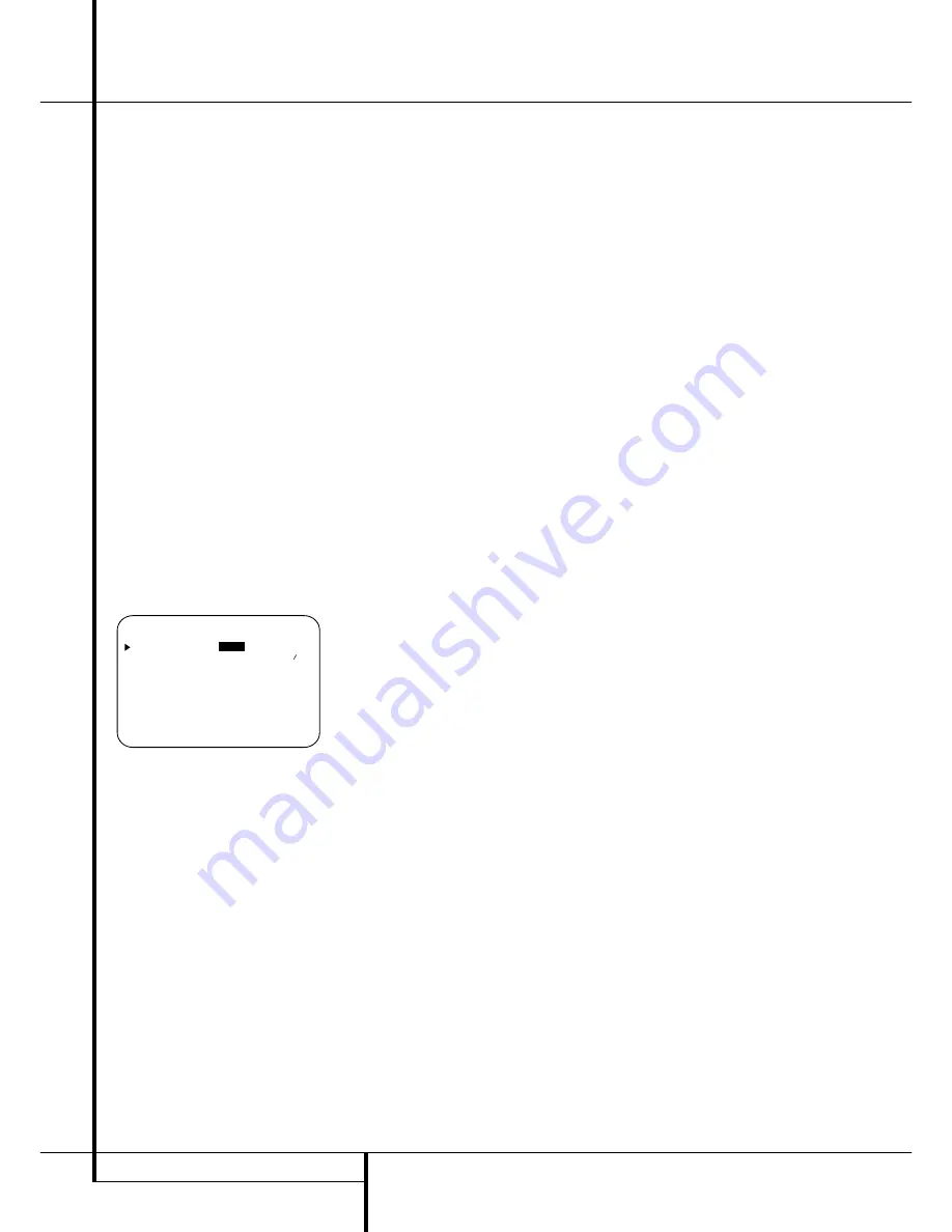
menu (Figure 12).
Figure 12
When the
MULTI-ROOM
menu appears, the
on-screen
›
cursor will be at the
MULTI-
ROOM
line. Since this line is used to turn the
system on and off, do not make an adjustment
here unless you wish to turn the system on at
this time. To turn the system on, press the
›
but-
ton
&
so that
O N
is highlighted. If you do not
wish to turn the system on at this time or to pro-
ceed to the next step, press the
¤
Button
D
once so that the
›
on-screen cursor is next to
the
MULTI I N
line.
At the
MULTI I N
line, press the
‹
/
›
buttons
E&
until the desired Audio/Video input to
the multi-room system appears in the highlight-
ed video. When the selection has been made,
press the
¤
button
D
once so that the
›
on-
screen cursor is next to the
MULTI VOL
line.
At the
MULTI VOL
line, press the
‹
/
›
but-
tons
E&
or hold them pressed until the
desired volume level for the multi-room system
is entered. DO NOT use the regular volume con-
trol knobs for this setting. When all settings for
the multiroom setup have been made, press the
¤
buttons
D
once so that the on-screen
›
cursor is next to the
BACK T O MASTER
MENU
line and press the
Set
button
F
. If
you have no other adjustments to make, press
the
OSD
button
L
to exit the menu system.
Multiroom Operation
When operating the AVR 4550 from a remote
room location where an IR sensor link has been
connected to the AVR 4550’s rear panel
Multiroom IR Input
, you may use either
the Main remote control or the Zone II remote.
To turn on the multiroom feed, press any of the
Input Selector
buttons on the Zone II remote
∫ç∂
or the Main remote
456
.
Press the
AVR Selector
5
∫
to turn the
unit on to the last source, or any of the other
Selector buttons to turn on to a specific source.
As long as an IR feed to the AVR 4550 has been
established from the remote room, using any of
the buttons on either remote will control the
remote location volume
)
î
, change the
tuner frequency
K
è
, change the tuner
preset
"
©
or mute the output
,
˚
.
If the
Remote IR Output
jack
on the
AVR 4550 is connected to an IR Input jack on
compatible Harman Kardon audio components
such as CD, DVD or cassette players, the trans-
port functions of those machines may also be
controlled using the
Transport Controls
P
Ƀ©˙∆
on either remote
control.
To turn the system off from the remote room,
press the
Power-Off
button
0
å
.
Remember that the AVR 4550 may be turned on
or off from the remote room regardless of the
system’s operation or status in the main room.
NOTE:
When the tuner is selected as the source
for the remote zone, any change to the frequen-
cy or preset will also change the station being
listened to in the main room, if the tuner is in
use there. Similarly, if someone in the main room
changes the station, the change will also impact
the remote room.
To activate the feed to the remote room, press
the
Multiroom
button
(
on the remote.
Next, press the
Set
button
F
. Press the
⁄
/
¤
buttons
D
to turn the multiroom feed on or
off. When the multiroom system is on, the
Multi
indicator
D
will light in the
Main Information
Display
˜
, and the
Main Information
Display
˜
or OSD will display
MULTI O N
.
Press the
Set
button
F
twice to enter the set-
ting.
When the multiroom system is turned on, the
input selected using the Multiroom Menu will be
fed to the
Multiroom Output
jacks
on the
rear panel as well as the
A-BUS Jack
.
The volume will be as set in the same menu,
although it may also be adjusted using an
optional IR sensor and the Zone II remote in the
remote location or on the optional audio power
amplifier connected to the
Multiroom Output
jacks
.
Once the multiroom system is turned on, it will
remain on even if the AVR 4550 is placed in the
Standby mode in the main room by pressing the
Power Off Button
0
or the
System Power
Control
2
on the front panel. To turn off the
multiroom system from the main listening room,
when the AVR is on press the
Multiroom
but-
ton
(
and then the Set button
F
. Press the
⁄
/
¤
buttons
D
so that the
Multi
indicator
D
in the
Main Information Display
˜
goes
out, and the
Main Information Display
˜
or
OSD will display
MULTI OFF
.
Even when the AVR is turned off (to Standby
mode) and the multiroom system is turned off
too, the multiroom system may be turned on at
any time by pressing the
Multiroom
button
(
, or any of the
Selector
buttons
∫ç
∂
in the remote room.
* M U L T I - R O O M *
M U L T I - R O O M :
O F F
O N
M U L T I I N : F M P R E S E T 0 1
M U L T I V O L : 2 2 5 d B
B A C K T O M A S T E R M E N U


