


FRONT-PANEL CONTROLS
FRONT-PANEL CONTROLS 7
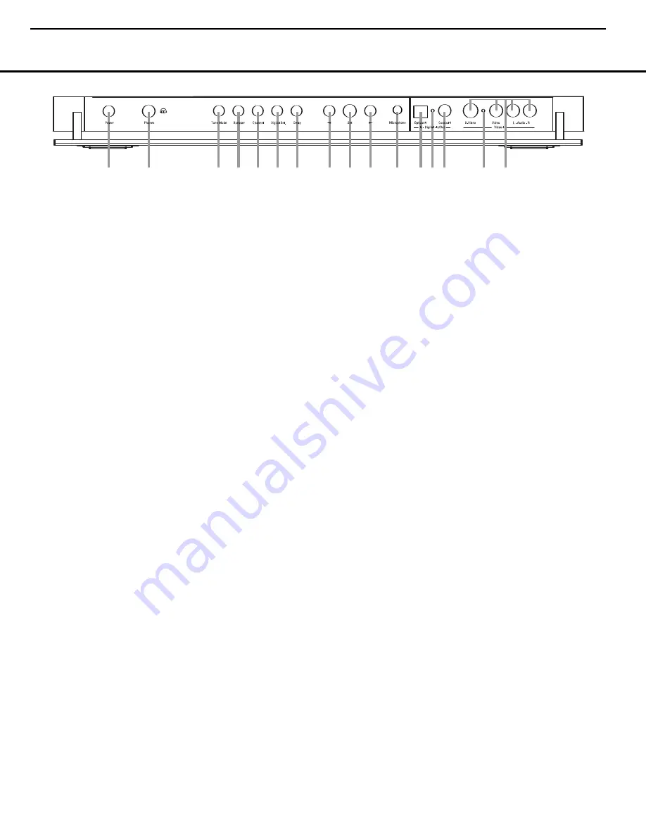
The following controls and jacks are located behind the front-panel door. To open the door, place the edge of a finger on the left or right edge of the panel and gently swing the
door down towards you.
A
Main Power Switch:
Press this switch to apply
power to the AVR
635
. When the switch is pressed
in, the unit is placed in a Standby mode, as indicated
by the amber illumination surrounding the
Standby/On
Switch
1
. This button MUST be pressed in to
operate the unit. To turn the unit off and prevent the
use of the remote control, this switch should be
pressed until it pops out from the front panel so that
the word “OFF” may be read at the top of the switch.
NOTE:
This switch is normally left in the “ON” position.
B
Headphone Jack:
This jack may be used to lis-
ten to the AVR
635
’s output through a pair of head-
phones. Be certain that the headphones have a stan-
dard 1/4" stereo phone plug, or that you use an
adaptor, as needed, to convert the plug on your head-
phones to the 1/4" jack used on the AVR. When the
headphone jack is in use, the main room speakers will
automatically be turned off and the unit will output a
standard stereo signal. You may also use one of the
Dolby Headphone modes for an enhanced listening
experience.
For more information on headphone lis-
tening, see page 33.
C
Tone Mode Button:
This button controls the tone
mode settings, enabling adjustment of the bass and
treble boost/cut. You may also use it to take the tone
controls out of the signal path completely for “flat”
response. The first press of the button displays a
TONE MODE
message in the
Lower Display
Line
$
and in the on-screen display. To take the
controls out of the signal path, press either of the
‹
/
›
Buttons
H
until the display reads
TONE
OUT
. To change the bass or treble settings, press
the button again until the desired option appears in the
Lower Display Line
$
and in the on-screen display
and then press either of the
‹
/
›
Buttons
H
to
enter the desired boost or cut setting.
See page 32
for more information on the tone controls.
D
Speaker Selector Button:
Press this button to
begin the process of configuring the AVR 635 for the
type of speakers it is being used with. For complete
information on configuring the speaker settings, see
page 27.
E
Channel Adjust Selector:
Press the button to
begin the process of adjusting the channel level out-
puts using the source currently playing through your
AVR.
For complete information on adjusting the chan-
nel output level, see page 30.
F
Digital Input Selector:
Press this button to begin
the process of selecting a digital source for use with
the currently selected input. Once the button has been
pressed, use the
‹
/
›
Buttons
H
to choose the
desired input and then press the
Set Button
I
to
enter the setting into the unit’s memory.
See page 33
for more information on digital audio.
G
Delay Adjust Selector:
Press this button to begin
the process of adjusting the delay settings for Dolby
surround modes.
See page 29 for more information
on delay adjustments.
H ‹
/
›
Buttons:
When making system configura-
tion changes using the front-panel controls, press
these buttons to scroll through the available choices
for the option being adjusted.
I
Set Button:
When making system configuration
changes using the front-panel controls, press this but-
ton to enter a setting into the unit’s memory.
J
EzSet/EQ Microphone Jack:
Before starting the
EzSet/EQ automated setup process, plug the micro-
phone into this jack. The microphone does not need
to be plugged in at other times.
K
Optical 4 Digital Input:
Connect the optical digital
output of an audio or video product to this jack.
L
Input/Output Status Indicators:
These LED
indicators will normally light green to show that the
front-panel
Coaxial 3 Digital Jack
L
and
Video 4
Input/Output Jacks
M
are operating as inputs. When
these jacks are configured for use as an output, the
appropriate indicator will turn red to show that the jack
may be used as an output for recording. (See page 38
for more information on configuring the front-panel
jacks as outputs, rather than inputs.)
M
Coaxial 4 Digital Jack:
Connect the coaxial digi-
tal input or output for a digital audio product such as a
portable audio player or video game to this jack. The
jack is normally an input, but may be switched to an
output for recording using the menu system.
See page
38 for more information.
N
Video 4 Input/Output Jacks:
These audio/video
jacks may be used as either an input or output for
temporary connection to video games or portable
audio/video products such as camcorders and
portable audio players.
(See page 38 for more
information on switching these jacks between an
input and output.)
A
B
D
E F
G
H
H
I
J
LM
N
C
L
K
AVR 635 OM 12/2/04 3:28 PM Page 7
AVR635 Only
= AVR635 Only
AVR435/635
harman/kardon
9
Summary of Contents for AVR 435
Page 27: ...AVR435 635 harman kardon 27 ...
Page 32: ...IDLE CURRENT sch 1 Tue Apr 19 19 52 22 2005 AVR435 635 harman kardon 32 ...
Page 33: ...h 1 Thu Mar 24 10 35 36 2005 33 ...
Page 34: ... Thu Mar 24 10 36 18 2005 34 ...
Page 80: ...80 ...
Page 81: ...5 SN74LVC1G125DVB DSP IC505 506 607 608 81 ...
Page 82: ...6 74VHC244M DSP IC504 7 ADV7172 VIDEO IC84 AVR635 ONLY 82 ...
Page 85: ...8 AT49BV162AT 70TI DSP IC902 85 ...
Page 86: ...9 BU4053BCF PROCESSOR IC606 VIDEO IC88 AVR635 ONLY 10 CS42518CQ DSP IC606 86 ...
Page 87: ...11 K4S161622H TC60 DSP IC903 87 ...
Page 88: ...88 ...
Page 89: ...12 UPD70F3033BGF DSP IC501 89 ...
Page 92: ...13 KIC9162AF PROCESSOR IC502 510 501 92 ...
Page 93: ...14 KIC9459F PROCESSOR IC204 507 93 ...
Page 94: ...15 LC74763M VIDEO IC75 AVR435 IC22 94 ...
Page 96: ...18 NJM317DL1 RMT 232 IC904 1 Adjustment 2 Output 3 Input 19 MAX3223CDWR RMT RS232 IC61 96 ...
Page 98: ...21 MM1234XFBE VIDEO IC33 AVR635 ONLY 22 MM1501XNRE VIDEO IC80 81 AVR435 IC14 25 26 98 ...
Page 99: ...23 MM1511XNRE VIDEO IC79 AVR435 IC27 24 NJM2296 VIDEO IC70 71 72 AVR435 IC10 11 12 99 ...
Page 101: ...26 NJM4556AD PROCESSOR IC601 27 PC 17T1 RMT RS232 IC651 652 DSP IC851 101 ...
Page 102: ...28 SN74HCU04D DSP IC704 705 29 TC9273F 004 PROCESSOR IC303 304 102 ...
Page 114: ...MISC 1 FL HCA 18LL03 FRONT DP1 2 2 114 ...
Page 115: ...VCXO 24M576HZ DSP Y600 3 TORX 179L DSP NJ701 702 703 4 TOTX 179L DSP NJ704 115 ...
Page 116: ...5 RPM6938 RSIP A3 FRONT RM71 6 LP 200TL FRONT RM72 1 2 3 116 ...
Page 117: ...AVR435 635 harman kardon 117 ...
Page 118: ...AVR435 635 harman kardon 118 ...
Page 119: ...AVR435 635 harman kardon 119 ...
Page 120: ...AVR435 635 harman kardon 120 ...
Page 121: ...AVR435 635 harman kardon 121 ...
Page 122: ...AVR435 635 harman kardon 122 ...
Page 123: ...AVR435 635 harman kardon 123 ...
Page 124: ...AVR435 635 harman kardon 124 ...
Page 125: ...AVR435 635 harman kardon 125 ...
Page 126: ...AVR435 635 harman kardon 126 ...
Page 127: ...AVR435 635 harman kardon 127 ...
Page 128: ...35_VIDEO_MP_SERVICE sch 1 Fri Mar 25 15 24 30 2005 128 ...
Page 129: ...35_VIDEO_MP_SERVICE sch 1 Fri Mar 25 15 16 28 2005 129 ...
Page 130: ...35_VIDEO_MP_SERVICE sch 2 Fri Mar 25 15 20 02 2005 AVR435 635 harman kardon 130 ...
Page 131: ...ERVICE sch 1 Fri Mar 25 15 11 15 2005 131 ...
Page 132: ...VICE sch 1 Fri Mar 25 15 17 46 2005 132 ...
Page 133: ...133 ...
Page 134: ...134 ...
Page 135: ...35DSP USA MP 050118 a sch 1 Tue Apr 19 14 34 19 2005 135 ...
Page 136: ...35DSP USA MP 050118 a sch 2 Tue Apr 19 14 34 37 2005 136 ...
Page 137: ...35DSP USA MP 050118 a sch 3 Tue Apr 19 14 34 44 2005 137 ...
Page 138: ...35DSP USA MP 050118 a sch 4 Tue Apr 19 14 34 49 2005 138 ...
Page 139: ... ڐڋڋڍٻڍڌڕڍڐڕڎڌٻڐڍٻۍڼڨٻۄۍڡٻڈٻڌڈۃھێډڔڌڍڌںګڨںگک AVR435 635 harman kardon 139 ...
Page 140: ... ڐڋڋڍٻڎڎڕڎڐڕڎڌٻڐڍٻۍڼڨٻۄۍڡٻڈٻڌڈۃھێډڌڌڋڌںګڨںۍۊێ AVR435 635 harman kardon 140 ...
Page 141: ... ڐڋڋڍٻڍڌڕڌڐڕڎڌٻڐڍٻۍڼڨٻۄۍڡٻڈٻڌڈۃھێډڍڍڋڌںګڨں AVR435 635 harman kardon 141 ...
Page 142: ... Thu Mar 24 10 26 13 2005 142 ...


