


SYSTEM CONFIGURATION 19
SYSTEM CONFIGURATION
When all audio, video and system connections have
been made, there are a few configuration adjustments
that must be made. A few minutes spent to correctly
configure and calibrate the unit will greatly add to your
listening experience.
Speaker Selection and Placement
The placement of speakers in a multichannel home
theater system can have a noticeable impact on the
quality of sound reproduced.
No matter which type or brand of speakers is used,
the same model or brand of speaker should be used
for the left front, center and right front speakers. This
creates a seamless front soundstage and eliminates
the possibility of distracting sonic disturbances that
occur when a sound moves across mismatched front
channel speakers.
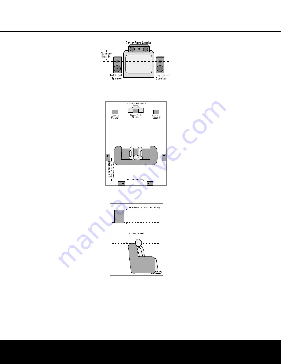
Speaker Placement
Depending on the type of center channel speaker in
use and your viewing device, place the center speaker
either directly above or below your TV, or in the center
behind a perforated front-projection screen.
Once the center channel speaker is installed, position
the front left and front right speakers so that they are
as far away from one another as the center channel
speaker is from the preferred listening position. Ideally,
the front channel speakers should be placed so that
their tweeters are no more than 24" above or below
the tweeter in the center channel speaker.
Depending on the specifics of your room acoustics
and the type of speakers in use, you may find that
imaging is improved by moving the left front and right
front speakers slightly forward of the center channel
speaker. If possible, adjust all front loudspeakers
so that they are aimed at ear height when you are
seated in the listening position.
Using these guidelines, you’ll find that it takes some
experimentation to find the correct location for the front
speakers in your particular installation. Don’t be afraid to
move things around until the system sounds correct.
Optimize your speakers so that audio transitions across
the front of the room sound smooth, and that sounds
from all speakers appear to arrive at the listening posi-
tion at the same time (without delay from the center
speaker compared to the left and right speakers).
When the AVR 435 is used in 5.1-channel operation,
the preferred location for surround speakers is on the
side walls of the room, at or slightly behind the listen-
ing position. In a 7.1-channel system, both side sur-
round and back surround speakers are required. The
center of the speaker should face into the room. The
A) Front-channel speaker installation with direct-view TV
sets or rear-screen projectors.
B) Rear speaker mounting is an alternate location for
5.1 systems. It is required for 7.1 operation.
speakers should be located so that the bottom of the
cabinet is at least 2 feet higher than the listeners’ ears
when the listeners are seated in the desired area.
Rear surround speakers are required when a full 7.1-
channel system is installed, and they may also be
used in 5.1-channel systems as an alternative mount-
ing position when it is not practical to place the main
surround speakers on the sides of the room. Speakers
may be placed on a rear wall, behind the listening
position. As with the side speakers, rear surrounds
should be located so that the bottom of the cabinet
is at least 2 feet higher than the listeners’ ears. The
speakers should be no more than 6 feet behind the
rear of the seating area.
If dipole-type speakers are used on either the side or
rear walls of the room, please note that if there are
arrows on the speakers they should face the front of
the room for the side speakers, or towards the center
of the wall for the rear speakers.
Subwoofers produce nondirectional sound, so they
may be placed almost anywhere in a room. Actual
placement should be based on room size and shape
and the type of subwoofer used. One method of find-
ing the optimal location for a subwoofer is to begin by
placing it in the front of the room, about 6 inches
from a wall, or near the front corner of the room.
Another method is to temporarily place the subwoofer
at your normal listening position, and then walk
around the room until you find a spot where the sub-
woofer sounds best. Place the subwoofer in that spot.
You should also follow the instructions of the sub-
woofer’s manufacturer, or you may wish to experi-
ment with the best location for a subwoofer in your
listening room.
System Setup
Once the speakers have been placed in the room and
connected, the remaining steps in the setup process
are to assign input and output connections, make any
tone adjustments, select a surround mode, program
the AVR 435’s bass management system for the type
of speakers used in your system, calibrate the output
levels and set the delay times used by the surround
sound processor.
Although it is necessary to assign input/output settings
and surround mode choices manually, we recommend
that you take advantage of the power and precision of
EzSet/EQ to automatically select and enter the settings
for all other audio parameters. This will not only save
you time; it will ensure that your room is calibrated and
equalized with an accuracy not possible when these
settings are made manually.
You are now ready to power up the AVR 435 to begin
these final adjustments.
1. Make certain that the AC power cord is firmly
inserted into the
AC Power Cord Jack
‹
and plug the cord into an unswitched AC outlet.
To maintain the unit’s safety rating, DO NOT
substitute the power cord for one with lower
current capacity.
AVR 435 OM 12/27/04 2:57 PM Page 19


