


FRONT-PANEL CONTROLS
FRONT-PANEL CONTROLS 7
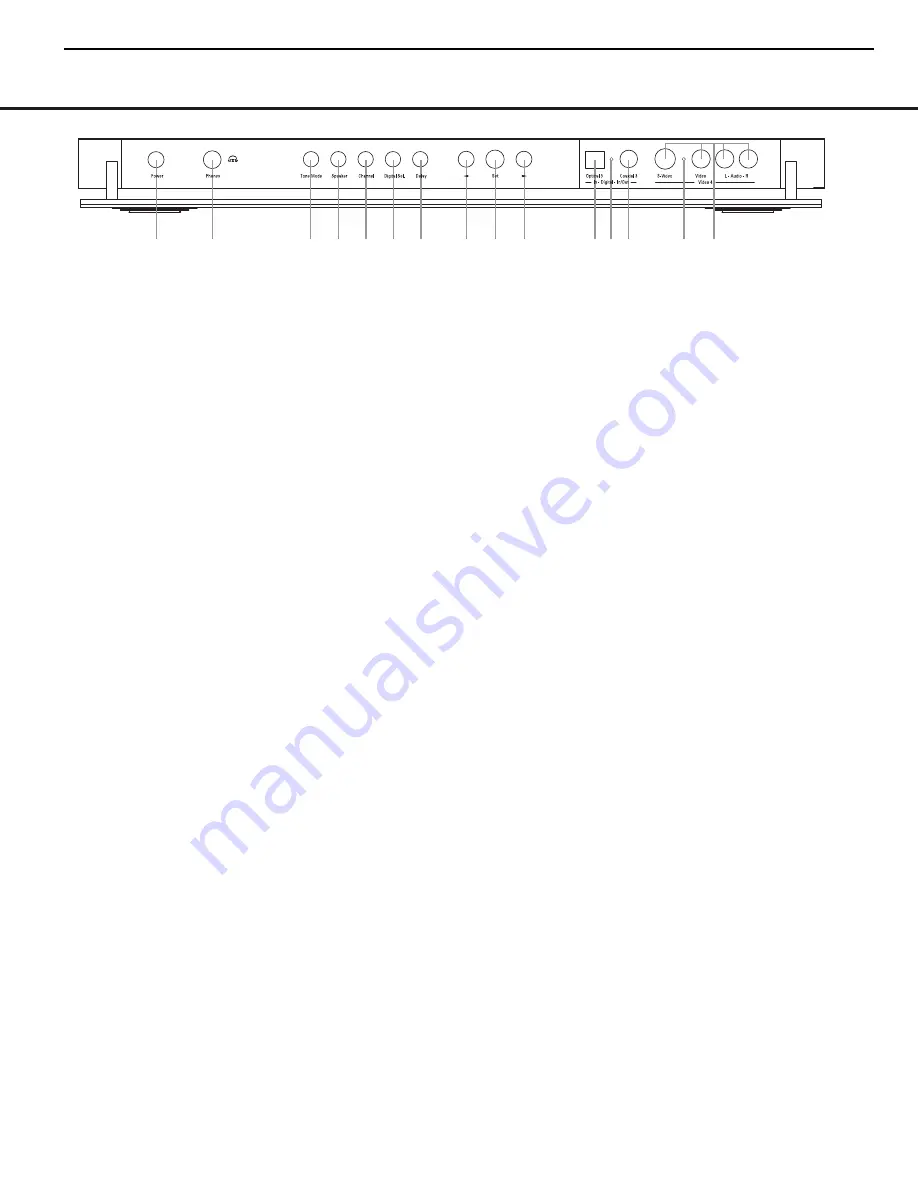
The following controls and jacks are located behind the front-panel door. To open the door, place the edge of a finger on the left or right edge of the panel and gently swing the
door down towards you.
A
Main Power Switch:
Press this switch to apply
power to the AVR
630
. When the switch is pressed
in, the unit is placed in a Standby mode, as indicated
by the amber illumination surrounding the
Standby/On
Switch
1
. This button MUST be pressed in to
operate the unit. To turn the unit off and prevent the
use of the remote control, this switch should be
pressed until it pops out from the front panel so that
the word “OFF” may be read at the top of the switch.
NOTE:
This switch is normally left in the “ON” position.
B
Headphone Jack:
This jack may be used to lis-
ten to the AVR
630
’s output through a pair of head-
phones. Be certain that the headphones have a stan-
dard 1/4" stereo phone plug, or that you use an
adapter, as needed, to convert the plug on your head-
phones to the 1/4" jack used on the AVR. When the
headphone jack is in use, the main room speakers will
automatically be turned off and the unit will output a
standard stereo signal. You may also use one of the
Dolby Headphone modes for an enhanced listening
experience.
For more information on headphone lis-
tening, see page 30.
C
Tone Mode Button:
This button controls the tone
mode settings, enabling adjustment of the bass and
treble boost/cut. You may also use it to take the tone
controls out of the signal path completely for “flat”
response. The first press of the button displays a
TONE MODE
message in the
Lower Display
Line
$
and in the on-screen display. To take the
controls out of the signal path, press either of the
‹
/
›
Buttons
H
until the display reads
TONE
OUT
. To change the bass or treble settings, press
the button again until the desired option appears in the
Lower Display Line
$
and in the on-screen display
and then press either of the
‹
/
›
Buttons
H
to
enter the desired boost or cut setting.
See page 30
for more information on the tone controls.
D
Speaker Selector Button:
Press this button to
begin the process of configuring the AVR
630
for the
type of speakers it is being used with.
For complete
information on configuring the speaker settings, see
page 23.
E
Channel Adjust Selector:
Press the button to
begin the process of adjusting the channel level out-
puts using the source currently playing through your
AVR.
For complete information on adjusting the chan-
nel output level, see page 35.
F
Digital Input Selector:
Press this button to begin
the process of selecting a digital source for use with
the currently selected input. Once the button has been
pressed, use the
‹
/
›
Buttons
H
to choose the
desired input and then press the
Set Button
I
to
enter the setting into the unit’s memory. See page 30
for more information on digital audio.
G
Delay Adjust Selector:
Press this button to begin
the process of adjusting the delay settings for Dolby
surround modes.
See page 25 for more information
on delay adjustments.
H ‹
/
›
Buttons:
When making system configura-
tion changes using the front-panel controls, press
these button to scroll through the available choices
for the option being adjusted.
I
Set Button:
When making system configuration
changes using the front-panel controls, press this but-
ton to enter a setting into the unit’s memory.
J
Optical 3 Digital Input:
Connect the optical digital
output of an audio or video product to this jack.
K
Input/Output Status Indicators:
These LED indi-
cators will normally light green to show that the front-
panel
Coaxial 3 Digital Jack
L
and
Video 4
Input/Output Jacks
M
are operating as inputs. When
these jacks are configured for use as an output, the
appropriate indicator will turn red to show that the jack
may be used as an output for recording.
(See page 34
for more information on configuring the front-panel
jacks as outputs, rather than inputs.)
L
Coaxial 3 Digital Jack:
Connect the coaxial digi-
tal input or output for a digital audio product such as a
portable audio player or video game to this jack. The
jack is normally an input, but may be switched to an
output for recording using the menu system.
See page
34 for more information.
M
Video 4 Input/Output Jacks:
These audio/video
jacks may be used as either an input or output for
temporary connection to video games or portable
audio/video products such as camcorders and
portable audio players.
(See page 34 for more
information on switching these jacks between an
input and output.)
A
B
D E F G
H
H
I
JK
K
L
M
C
= AVR630 only feature
AVR430/AVR630
harman/kardon
8
Summary of Contents for AVR 430
Page 18: ... Tue Jan 13 17 16 23 2004 0 harman kardon 18 ...
Page 19: ...sch 1 Tue Jan 13 17 17 50 2004 harman kardon 19 ...
Page 28: ...AVR630_block_MP sch 1 Mon Jan 12 14 41 38 2004 28 ...
Page 29: ...29 ...
Page 78: ...8 UPD70F3033BGF DSP PART IC600 AVR430 AVR630 harman kardon 78 ...
Page 83: ...22 TSH95 VIDEO PART IC17 23 MPD4721 VIDEO PART IC50 AVR430 AVR630 harman kardon 83 ...
Page 84: ...24 K4S161622D TC80 DSP PART IC805 AVR430 AVR630 harman kardon 84 ...
Page 86: ...27 2C74763M VIDEO PART IC22 28 FL HCA 18LL03 FRONT PART DP10 AVR430 AVR630 harman kardon 86 ...
Page 87: ...3 PROCESSOR APRT IC6 IC10 AVR430 AVR630 harman kardon 87 ...
Page 90: ...CS49400 DSP PART IC800 AVR430 AVR630 harman kardon 90 ...
Page 99: ...AVR430 AVR630 harman kardon 99 ...
Page 103: ...DSP BOARD TOP VIEW AVR430 AVR630 harman kardon 103 ...
Page 104: ...DSP BOARD BOTTOM VIEW AVR430 AVR630 harman kardon 104 ...
Page 105: ...PROCESSOR BOARD TOP VIEW AVR430 AVR630 harman kardon 105 ...
Page 106: ...PROCESSOR BOARD BOTTOM VIEW AVR430 AVR630 harman kardon 106 ...
Page 107: ...MAIN AMP BOAR D AVR430 AVR630 harman kardon 107 ...
Page 108: ...FRONT BOARD BOTTOM VIEW AVR430 AVR630 harman kardon 108 ...
Page 109: ...FRONT BOARD TOP VIEW AVR430 AVR630 harman kardon 109 ...
Page 110: ...VIDEO BOARD BOTTOM VIEW AVR430 AVR630 harman kardon 110 ...
Page 111: ...VIDEO BOARD TOP VIEW AVR430 AVR630 harman kardon 111 ...
Page 112: ...SUPPLY BOARD AVR430 AVR630 harman kardon 112 ...
Page 113: ...BACK SURROUND BOARD AVR430 AVR630 harman kardon 113 ...
Page 114: ...114 ...
Page 115: ...115 ...
Page 116: ...116 ...
Page 117: ...117 ...
Page 118: ...118 ...
Page 119: ...119 ...
Page 120: ...120 ...
Page 121: ...121 ...
Page 122: ...122 ...
Page 123: ... æ ˆł œ ı æ AVR430 AVR630 harman kardon 123 ...
Page 124: ... æ ˆł ı æ AVR430 AVR630 harman kardon 124 ...
Page 125: ...125 ...


