background image

17

17

CONNECTIONS

Audio Connections

There are two formats for audio connections: digital and analog. Digital
audio signals are of higher quality, and are required for listening to
sources encoded with digital surround modes, such as Dolby Digital and
DTS. There are two types of digital audio connections: coaxial and opti-
cal. Either type of digital audio connection may be used for each source
device, but never both simultaneously for the same source. However, it’s
okay to make both analog and digital audio connections at the same
time to the same source.

NOTE

: Although HDMI cables are capable of carrying digital

audio signals, the AVR 245 is not designed to process those
signals. Therefore, if your source and video display are both
HDMI-capable, use the HDMI connections for video only. You
will need to make a separate audio connection from the source
device to the AVR 245, and you should make sure to turn the
volume on your television all the way off.
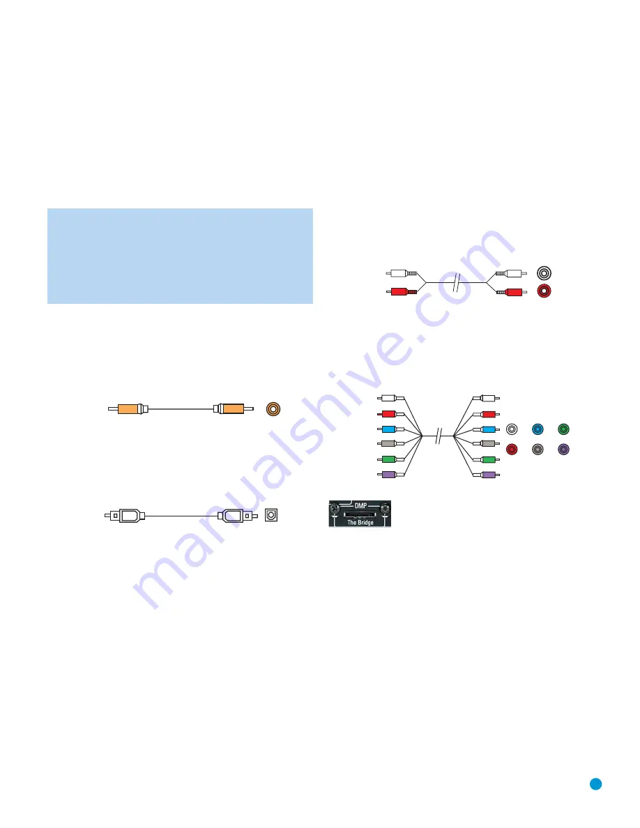
Digital Audio

Coaxial digital audio jacks are usually color-coded in orange. Although
they look similar to analog jacks, they should not be confused, and you
should not connect coaxial digital audio outputs to analog inputs or 
vice versa. See Figure 4.

Figure 4 – Coaxial Digital Audio

Optical digital audio connectors are often covered by a shutter to protect
them from dust. The shutter opens as the cable is inserted. Input con-
nectors are color-coded using a black shutter, while outputs use a gray
shutter. See Figure 5.

Figure 5 – Optical Digital Audio

Due to the nature of digital signals as binary bits, they aren’t subject 
to signal degradation the way analog signals are. Therefore, the quality
of coaxial and optical digital audio connections should be the same,
although it is important to limit the length of the cable. Whichever type of
connection you choose, Harman Kardon recommends that you always
select the highest quality cables available within your budget.

Analog Audio

Analog connections require two cables, one for the left channel (white)
and one for the right channel (red). These two cables are often attached
to each other for most of their length. See Figure 6.

Most sources that have digital audio jacks also have analog audio jacks,
although some older types of sources, such as tape decks, have only
analog jacks. For sources that are capable of both digital and analog
audio, you may wish to make both connections.

The analog audio connection is strongly recommended if you intend to
use the source with the multiroom system. It’s required if you will be
using the multiroom preamp outputs with an external amplifier to power
your remote speakers, as the AVR 245’s multiroom system is not capa-
ble of converting the digital signal to analog format. It’s suggested that
you also use the analog audio connections when using the surround
back/multiroom speaker outputs, in case another two-channel digital
audio source is in use in the main listening area. The AVR 245 is only
capable of processing one PCM source at a time.

If you wish to record materials from DVDs or other copy-protected
sources, you may only do so using analog connections. (Remember to
comply with all copyright laws, if you choose to make a copy for your
own personal use.) 

Figure 6 – Analog Audio

Multichannel analog connections are used with advanced sources where
the digital content is copy-protected and all surround processing is per-
formed inside the source. These types of connections are usually used
with DVD-Audio, SACD, Blu-ray Disc, HD-DVD and other advanced 
players. See Figure 7.

Figure 7 – Multichannel Analog Audio

Figure 8 – The Bridge

Harman Kardon receivers also include a proprietary, dedicated audio
connection called “The Bridge/DMP”. If you own an iPod with a dock
connector, you may separately purchase The Bridge and connect it to
The Bridge/DMP port on the receiver. See Figure 8. Dock your iPod
(not included) in The Bridge, and you may listen to your audio materials
through your high-performance audio system. You may even use the
AVR 245 remote to control the iPod, with navigation messages dis-
played on the front panel and on a video display connected to the AVR.

Video Connections

Although some sources produce an audio signal only (e.g., CD player,
tape deck), many sources output both audio and video signals (e.g.,
DVD player, cable television box, HDTV tuner, satellite box, VCR, DVR).
In addition to the audio connection, you will need to connect one type of
video connection for each source (never more than one at the same
time for any source).

Multichannel
analog audio
cable (R

C

A)

Front  

S

urround  

C

enter

S

ubwoofer

L

R

Analog audio
cable (R

C

A)

Optical

Optical digital
audio cable

C

oaxial

C

oaxial digital

audio cable

HKP1477AVR245om  8/29/06  5:46 PM  Page 17

Summary of Contents for AVR 245

Page 1: ... Designed to Entertain AVR 245 AUDIO VIDEO RECEIVER OWNER S MANUAL ...

Page 2: ...UNCTIONS 42 Audio Processing and Surround Sound 42 Analog Audio Signals 42 Digital Audio Signals 43 Surround Modes 44 Dolby Surround Settings 44 Default Modes 48 Manual Setup 48 Step One Determine Speaker Size 48 Step Two Measure Speaker Distances 48 Step Three Manual Setup Menu 49 Speaker Size Menu 50 Speaker Crossover Menu 50 Delay Adjust Menu 51 Step Four Setting Channel Output Levels Manually ...

Page 3: ...nna or cable system is grounded so as to provide some protection against voltage surges and built up static charges Article 810 of the National Electrical Code ANSI NFPA 70 provides information with regard to proper grounding of the mast and supporting structure grounding of the lead in wire to an antenna discharge unit size of grounding conductors location of antenna discharge unit connection to ...

Page 4: ...terials that may be damaged by heat or heavy objects Some surface finishes may be particularly sensitive to absorbing such marks due to a variety of factors beyond Harman Kardon s con trol including the nature of the finish cleaning materials used and normal heat and vibration caused by the use of the product or other factors We recommend that caution be exercised in choosing an installation locat...

Page 5: ...t s serial number At the same time you can choose to be notified about our new products and or special promotions AVR 245 7 1 Channel Audio Video Receiver Audio Section 50 Watts x 7 seven channels driven at full power at 8 ohms 20Hz 20kHz 0 07 THD surround modes 350 watts total 65 Watts x 2 two channels driven at full power at 8 ohms 20Hz 20kHz 0 07 THD surround off mode 130 watts total High curre...

Page 6: ...dot matrix front panel display Color coded connections Programmable 11 device main remote control Source input renaming A V Sync Delay RS 232 serial port for system upgrades Switched accessory power outlet Remote infrared IR input and output Multiroom IR input Supplied Accessories The following accessory items are supplied with the AVR 245 If any of these items are missing please contact Harman Ka...

Page 7: ...l weather and local temporature Preset Stations Press this button to select a preset radio station Headphone Jack EzSet Microphone Input Plug a 1 4 headphone plug into this jack for private listening This jack is also used to connect the supplied microphone before begin ning the EzSet procedure described in the Initial Setup section To begin EzSet plug the supplied microphone into this jack place ...

Page 8: ...er Size Setup Delay Digital Input Select Power Indicator Main Power Switch Standby On Switch Volume Source Indicators Message Display Surround Mode Indicators Speaker Channel Input Indicators Channel Level Adjust NOTE To make it easier to follow the instructions throughout the manual that refer to this illustration a copy of this page may be downloaded from the Product Support section at www harma...

Page 9: ...ne of a multiroom system to this jack to control the AVR and any source devices connected to the Remote IR Output from the remote zone Video 1 Video 2 Video 3 and DVD Audio Video Inputs These jacks may be used to connect your video capable source components e g VCR DVD player cable TV box to the receiver Remember to use only one type of video connection for each source See the Connections section ...

Page 10: ...n your video display You will also need to connect the composite and or S video monitor outputs to your video display to view the AVR 245 s on screen displays RS 232 Serial Port This specialized connector may be used with your personal computer in case Harman Kardon offers a software upgrade for the receiver at some time in the future RS 232 Mode Leave this switch popped out in the Operate positio...

Page 11: ...eamp Outputs Front Speaker Outputs Surround Speaker Outputs 6 8 Channel Inputs Surround Back Multiroom Speaker Outputs Surround Back Multiroom Preamp Outputs Center Speaker Outputs Switched AC Accessory Outlet Coaxial Digital Audio Output Optical Digital Audio Inputs 1 2 Optical Digital Audio Output CD Inputs Multiroom IR Input Remote IR Input Remote IR Output Tape Outputs Tape Inputs NOTE To make...

Page 12: ...ling a televi sion or cable box See Table A8 in the appendix for listings of the different functions for each type of component IR Transmitter Lens As buttons are pressed on the remote infrared codes are emitted through this lens Make sure it is pointing toward the component being operated Power On Button Press this button to turn on the AVR or another device The Master Power Switch on the AVR 245...

Page 13: ...ransport Controls Power Off Mute Input Selectors 6 Channel Input Selector TV Video Volume Control Not Used Speaker Setup Set Numeric Keys Delay Memory Clear Preset Stations Selectors Disc Skip Macros Surround Mode Selectors Dim NOTE To make it easier to follow the instruc tions throughout the manual that refer to this illustration a copy of this page may be down loaded from the Product Support sec...

Page 14: ... To save the current channel in one of the 40 available preset locations press the Set Button repeatedly until PRESET SEARCH appears Use the Buttons to select a letter A through E representing one of the five banks of preset memory slots Then press the Memory button followed by a Numeric Key 1 through 8 for the precise preset memory location you wish to save the channel in Tuning Press these butto...

Page 15: ...o set up a 5 1 channel system in your main listening area and reassign the surround back channels for use with a multiroom system in which you use the surround back channels to power a pair of loudspeakers located in another room Many people expect the surround speakers to play as loudly as the front speakers Although all of the speakers in the system will be cali brated to sound equally loud at t...

Page 16: ...he collar is revealed 2 Insert the bare end of the wire into the hole 3 Hand tighten the cap until the wire is held snugly Figure 2 Binding Post Speaker Terminals With Bare Wires Subwoofer The subwoofer is a specialized type of loudspeaker that is usually con nected in a different way The subwoofer is used to play only the low frequencies bass which require much more power than the other speaker c...

Page 17: ...es of sources such as tape decks have only analog jacks For sources that are capable of both digital and analog audio you may wish to make both connections The analog audio connection is strongly recommended if you intend to use the source with the multiroom system It s required if you will be using the multiroom preamp outputs with an external amplifier to power your remote speakers as the AVR 24...

Page 18: ...connection most commonly available The jack is usually color coded yellow and looks like an analog audio jack although it is important never to confuse the two Do not plug a com posite video cable into an analog or coaxial digital audio jack or vice versa Both the chrominance color and luminance intensity compo nents of the video signal are transmitted using a single cable See Figure 10 Figure 10 ...

Page 19: ...toward the listener If this isn t feasible place the surround speakers behind the listener with each surround speaker facing the opposite side front speaker See Figure 15 The surround speakers may be placed a little higher than the listener s ears Placement of Surround Speakers in a 7 1 Channel System In a 7 l channel system the side surround speakers are placed 90 degrees from the center speaker ...

Page 20: ...ofer close to a wall or in a corner will reinforce the low frequencies and may create a boomy sound You may wish to experiment over time by placing the subwoofer where the listener normally sits and then walking around the room until the low frequencies sound best Place the subwoofer in that spot NOTE Your receiver will sound its best when the same model loudspeaker is used for all positions other...

Page 21: ...ource Components Use the worksheets in the Appendix to note which connections you will use for each of your source devices For each source select a source input Video 1 Video 2 Video 3 etc In Table 2 we recommend connecting certain types of sources to certain source inputs to make it easier to program and use the remote control Decide which audio connections you will use If your source device has ...

Page 22: ...ing coax composite video output and do not use or optical digital output component video connections at all Cable TV satellite TV Video 2 Video 2 Analog and One of component Video 3 Video 2 HDTV or other Optical 1 S video or Video 2 composite video device that delivers television programs TV or other Video 3 Video 3 Analog and Video 3 S video or Video 3 composite audio video device Any one availab...

Page 23: ...to the Video 3 inputs and use the device s own remote to control it If you receive your television programming using your TV with an antenna or direct cable connection then you will need to connect the analog audio outputs if available on your TV to the Video 3 Analog Audio inputs See Figure 22 Do not connect any video output on the television set to any video input on the receiver See Step Five f...

Page 24: ...eo Interface input you may use an HDMI to DVI adapter not included Figure 26 HDMI and Coaxial 2 Inputs HDMI 2 Source The HDMI 2 source is used with a second device that is capable of out putting digital video through an HDMI connection such as an HD DVD or Blu ray Disc player The HDMI 2 source is not used with any of the 2 channel analog audio or video inputs on the AVR 245 Since the AVR 245 is no...

Page 25: ...o for any sources connect the Component Video Monitor outputs on the receiver to one set of component video inputs on your display See Figure 32 Make a note of how these inputs are labeled on the display Figure 32 Component Video Monitor Outputs If you used S video for any sources or if all of your sources used HDMI or component video connect the S video Monitor output on the receiver to an S vide...

Page 26: ...nd turns on the device programmed for that source press the Input Selector a second time The Input Selector will light in green to indicate that the secondary source is active The AVR 245 s remote is factory programmed to control an iPod docked in The Bridge and many Harman Kardon DVD and CD players If you have other source devices in your system follow these steps to program the correct codes int...

Page 27: ...e describe the button s function when used to control the AVR 245 However the button may perform a very different function when used to control another device Refer to the Remote Control Function List Table A8 in the Appendix for a list of each button s functions with the various product types If you wish you may program Macros which are preprogrammed code sequences that execute many code commands...

Page 28: ...electors on the remote i e DVD CD TAPE The Bridge HDMI 1 HDMI 2 VID1 VID2 VID3 or VID4 the remote will switch modes so that it will only transmit the codes programmed to operate that device In order to control the receiver you will need to press the AVR button to return the remote to AVR mode ...

Page 29: ...Buttons to navigate to another line item Except for the TITLE setting in the INPUT SETUP menu there is no need to press the Set Button after your desired setting appears NOTE The and Set Buttons on the front panel have no effect on the OSD system The Master Menu allows access to six submenus Input Setup Surround Select EzSet Manual Setup Multi room and System Setup See FIgure 41 Figure 41 Master M...

Page 30: ...put Jack on the front of the receiver See Figure 42 Figure 42 Plug EzSet microphone into receiver Step Three Make sure that the AVR 245 and the video display are turned on Press the OSD Button to display the Master Menu See Figures 40 and 41 Use the Buttons to move the cursor to the EzSet line and then press the Set Button to select the EzSet menu See Figure 43 Figure 43 EzSet Menu Screen The curs...

Page 31: ...not coming from the correct speaker press the Button on the remote to stop EzSet The cursor will move to the BACK TO MASTER MENU line giv ing you an opportunity to exit the on screen menu system and turn off the AVR so that you can check your speaker connections Figure 49 EzSet Speaker Check NOTE EzSet can only detect the presence of a speaker not its location within the room If your speakers are ...

Page 32: ... all of these tests a screen similar to the one in Figure 52 will appear The TEST DONE UNPLUG MIC mes sage will disappear after a few seconds replaced by a speaker channel name You may move the cursor to that line and scroll through the speaker channels to review the EzSet results If they are satisfactory return the cursor to the SAVE SETTING line and press the Set Button to save the EzSet setting...

Page 33: ... is not processed or upscaled AUDIO IN By default the analog audio inputs are assigned at the factory to all sources with the following exceptions Table 4 Default Digital Audio Assignments If you used a digital audio connection for another source you will need to change this setting to assign the correct digital audio input to the source even if you also connected the analog audio outputs of the s...

Page 34: ...ccess the DMP SETTING menu you need to press the AVR Selector on the remote so that it operates the AVR 245 You may then press the OSD Button and use the Navigation and Set Buttons as usual with the on screen menu system When you are ready to return to operation of your iPod using the remote remember to press the DMP The Bridge Selector so that the transport and other controls operate The Bridge T...

Page 35: ...n and pre set radio stations will be preserved for up to four weeks Sleep Timer You may program the AVR to play for up to 90 minutes and then turn off automatically using the sleep timer Press the Sleep Button on the remote and the time until turn off will be displayed See Figure 60 Each additional press of the Sleep Button will reduce the time until turn off by 10 minutes until the OFF setting is...

Page 36: ...o make other changes using the menu system NOTE The AVR 245 does not have a conventional balance control The EzSet process compensates for any characteris tics of your room or speakers and we recommend that you leave the settings as they are after EzSet has been run However you may manually adjust the levels of the left and right channels decreasing one and increasing the other by the same amount ...

Page 37: ...he Component Video 3 input is assigned to the Video 2 source All other sources default to the CONVERT setting meaning that they may only be used with their composite or S video inputs or the HDMI inputs for the two HDMI sources The AVR 245 will transcode the incoming composite or S video signal and make it available using the component video monitor outputs enabling a single cable connection to yo...

Page 38: ...TE The 6 8 Channel Inputs pass the incoming signals directly to the volume control without digitizing or processing them Therefore you will need to configure bass management settings i e speaker size delay and output level on your source device so that they match the settings you programmed using EzSet which may be viewed using the Manual Setup menu see Advanced Functions section Consult the owner...

Page 39: ...ly using the Numeric Keys on the remote It is not necessary to press the Direct Button first 2 Press the Tuning Buttons on the front panel or remote to scan through the channels 3 The AVR 245 is capable of storing up to 40 XM Radio preset channels The presets are divided into five banks denoted by the letters A through E with eight numeric presets per bank After you have programmed preset stations...

Page 40: ...s front panel or a connected video display and charge the iPod Either press the front panel Source Selector repeatedly until the mes sage DMP The Bridge is CONNECTED scrolls across the front panel and semi OSD displays or press the DMP Button on the remote to select The Bridge as the input source Figure 73 Using The Bridge Remote Figure 74 Using The Bridge Front Panel Table 5 summarizes the contro...

Page 41: ...ode Front Panel To select a surround mode using the remote control locate the button dedicated to the desired group of modes Logic 7 Dolby Sur DTS Sur DTS Neo 6 Surr DSP or Stereo Press that button repeatedly to select the desired mode See Figure 76 To select a surround mode using the full OSD menu system press the OSD Button to display the Master Menu Navigate to the SURROUND SELECT line and pres...

Page 42: ...he available modes are the Dolby Pro Logic II and IIx modes the Dolby Virtual Speaker modes the DTS Neo 6 modes the Logic 7 modes the Hall and Theater modes and the Stereo modes Digital Audio Signals Digital audio signals offer the benefit of greater capacity which allows recording artists to encode center and surround channel information directly into the signal The result is improved sound quali...

Page 43: ...ites www dolby com and www dtsonline com When in doubt check the jacket of your DVD for more information on which surround modes are available on the disc Be aware that usually nonessential sections of the disc such as trailers extra materials or the disc menu are only available in Dolby Digital 2 0 2 channel or PCM 2 channel mode If the main title is playing and the letters in the Speaker Channel...

Page 44: ...h the three settings with the selected setting being dis played on the front panel and in the semi OSD display UPSAMPLING The last line of the Surround Select menu activates upsampling only available with the Dolby Pro Logic II IIx Movie Dolby Pro Logic II IIx Music and Dolby Pro Logic modes Normally set to OFF upsampling when activated processes digital sources at a higher reso lution for improve...

Page 45: ...Dolby Pro Logic II that is optimized for music selections Dolby Digital 2 0 or 2 1 Music Allows adjustment of sound field presentation in three dimensions Analog 2 channel Center Width adjusts width of vocal soundstage Tuner Dimension adjusts depth of soundstage PCM 44 1kHz 48kHz 96kHz Panorama adjusts wraparound surround effect Dolby Pro Logic II Variant of Dolby Pro Logic II that emphasizes use ...

Page 46: ...ode may be used with two three four or five main speakers to widen Dolby Digital number of channels available Wide the front soundstage by virtualizing the locations of the left and right speakers varies by number of channels in signal Analog 2 channel Tuner PCM 44 1kHz or 48kHz DTS Digital Using a different encoding decoding method than Dolby Digital it also DTS 1 0 0 or 1 2 0 0 or 1 3 0 0 or 1 p...

Page 47: ...ce circulates low frequencies in the 40Hz 120Hz range to Analog 2 channel Enhance the main speakers for less localized bass performance than would be achieved Tuner solely with a subwoofer Enhance mode is best used with music recordings PCM 44 1kHz 48kHz 96kHz Hall 1 Hall 1 is a DSP digital signal processor mode that simulates a small Analog 2 channel concert hall It is available in 5 or 6 channel...

Page 48: ...R 245 is to program the receiver s bass management which determines which speakers the receiver will use to play back the low frequency bass portion of the source program If you send the lowest notes to small satellite speakers you won t hear these notes very well and you may even damage the speaker by going beyond its capabilities If you send the highest notes to the special pur pose subwoofer yo...

Page 49: ...cessor You may use the SMALL setting instead As you listen to the receiver if you find the SMALL setting is not satisfactory change the surround mode to one of the Dolby Pro Logic II modes using the Surround Select menu accessible from the Master Menu and return to this menu to change the center speaker to the LARGE setting SURROUND Move the cursor to the line for the side surround speakers and us...

Page 50: ...e Figure 82 Figure 82 Speaker Channel Input Indicators Speaker Crossover Menu On the Manual Setup menu move the cursor to the SPEAKER X OVER line and press the Set Button to display the Speaker Crossover menu See Figure 83 Figure 83 Speaker Crossover Menu Screen Setting the Speaker Crossover menu correctly ensures that your speakers are properly used so that they sound their best Although you coul...

Page 51: ... Button and the A V SYNC DELAY message will appear on the front panel and in the semi OSD display Press the Set Button to display the current delay setting and use the Buttons to adjust the setting until the picture and sound are back in sync Move the cursor to the BACK TO MANUAL SETUP line and press the Set Button to return to the Manual Setup menu You may adjust the delay settings without using ...

Page 52: ...hat does not utilize all speakers such as Surround Off you will see dashed lines next to the speakers that aren t needed for that mode CHANNEL RESET If you wish to start by resetting all of the levels to their factory defaults of 0dB navigate to this line and change the setting to ON The levels will be reset and this setting will then revert to OFF If you are using an external source to set your o...

Page 53: ...o the main listening room for 7 1 channel operation You may install an optional remote infrared IR receiver in the remote room and connect it to the Multiroom IR Input on the back of the receiver This lets you use an optional second zone remote keypad or other control device to turn the multiroom system on or off select a source input and operate any source devices that are connected in daisychain...

Page 54: ...ams in the Dolby Pro Logic II Movie surround mode then set DEFAULT SURR MODE to OFF and select the Dolby Pro Logic II Movie surround mode the first time a Dolby Digital 2 0 program is played Dolby Digital 5 1 programs will still be played in 5 1 channel mode NOTE For PCM and analog sources the factory default surround mode is Logic 7 Music In general the receiver will use the surround mode selecte...

Page 55: ...before you enter commands to be transmitted to that device This step counts as one of the 19 commands allowed for each macro 3 For the Power On command DO NOT press the Power On Button Press the Mute Button instead 4 Press the Power Off Button to program the Power Off command 5 Press the Sleep Button to end the programming process It isn t possible to edit a command within a macro However you may ...

Page 56: ... Remote IR Output connected to the next device s Remote IR Input and so forth NOTE Not all remote controllable devices are equipped with compatible IR inputs and outputs Check with the manufacturer of the source device for more information on the type of IR signal expected The AVR 245 will output a stripped carrier IR signal Resetting the Remote To reset the remote to its factory defaults enter Pr...

Page 57: ... to remote or connect an optional remote sensor Intermittent buzzing in tuner Local interference Move unit or antenna away from computers fluorescent lights motors or other electrical appliances Letters flash in the channel indicator Digital audio feed paused Resume play for DVD display and digital audio stops Check that Digital Input is selected Surround Back Speaker settings Multiroom system has...

Page 58: ...ption 65W idle 540W maximum 5 channels driven Dimensions Product Shipping Width 17 5 16 inches 440mm 21 7 8 inches 555mm Height 6 1 2 inches 165mm 10 1 2 inches 266mm Depth 15 inches 382mm 18 5 16 inches 465mm Product Shipping Weight 30 0 lb 13 6kg 35 0 lb 15 9kg Depth measurement includes knobs buttons and terminal connections Height measurement includes feet and chassis All features and specific...

Page 59: ... Channel Setting Defaults Source DVD HDMI 1 HDMI 2 Video 1 Video 2 Video 3 Video 4 The Bridge CD Tape Tuner 6 8 XM DMP Channel Bass Manager Global Left Right Speaker Size Small Small Small Small Small Small Small Small Small Small Small Large Small Center Speaker Size Small Small Small Small Small Small Small Small Small Small Small Large Small Surround Speaker Size Small Small Small Small Small S...

Page 60: ...Left Right Speaker Size N A Center Speaker Size N A Surround Speaker Size N A Subwoofer N A Left Right Speaker Crossover N A Center Speaker Crossover N A Surround Speaker Crossover N A Subwoofer Crossover N A Left Right Channel Level Center Channel Level Surround Channel Level Subwoofer Channel Level The 6 8 Channel Inputs are direct inputs meaning their signals are passed directly to the volume c...

Page 61: ...Video 2 Cable Satellite Video 3 TV Video 4 DVD DVD CD CD CDR Tape Cassette HDMI 1 HDMI 2 Table A7 System Settings Feature Default Setting Your Setting VFD Fade Time Out Off Volume Default Off Default Vol Set 25dB Semi OSD Time Out 5 seconds Full OSD Time Out 20 seconds Default Surr Mode On OSD Background Blue APPENDIX ...

Page 62: ...30 31 32 33 34 35 36 37 38 39 40 41 42 43 44 45 46 47 48 49 50 51 52 53 54 55 56 57 58 59 60 61 62 63 64 65 66 67 68 69 70 26 28 21 18 22 Refer to the numbered buttons in Figure 88 when using the Function List Figure 88 Remote Control Function List Reference APPENDIX ...

Page 63: ...ect Video 4 Select Video 4 Select Video 4 Select Video 4 Select Video 4 Select Video 4 Select Video 4 Select Video 4 Select Video 4 Select 12 XM XM Select XM Select XM Select XM Select XM Select XM Select XM Select XM Select XM Select XM Select XM Select XM Select 13 AM FM Tuner Select Tuner Select Tuner Select Tuner Select Tuner Select Tuner Select Tuner Select Tuner Select Tuner Select Tuner Sel...

Page 64: ...o 3 Macro 3 Macro 3 Macro 3 55 M4 Macro 4 Macro 4 Macro 4 Macro 4 Macro 4 Macro 4 Macro 4 Macro 4 Macro 4 Macro 4 Macro 4 56 Dolby Surround Dolby Modes 57 DTS Surround DTS Digital Modes 58 DTS Neo 6 DTS Neo 6 Select 59 Night Night Mode Select Subtitle On Off CDP Select 60 Logic 7 Logic 7 Select 61 Stereo Stereo Mode Select 62 Skip Down Skip DVD Step Skip Scan Thumbs Down Skip DVD Skip DVD Skip DVD...

Page 65: ... 114 116 119 127 128 132 DAYTRON 128 132 DIGI LINK 200 DYNASTY 045 DYNATECH 063 ELECTROHOME 115 132 EMERSON 045 123 128 132 139 157 158 159 162 205 FUNAI 045 FUTURETECH 045 GE 029 087 121 123 128 133 145 159 163 GOLDSTAR LG 101 110 122 128 132 GRUNDIG 193 HALL MARK 128 HARMAN KARDON 201 HITACHI 123 128 132 144 147 INFINITY 148 INKEL 120 JBL 148 JC PENNEY 115 123 128 132 145 JENSEN 019 JVC 079 087 ...

Page 66: ...CO 045 115 123 128 132 148 PHILIPS 033 035 036 123 128 132 145 148 PIONEER 024 123 128 PORTLAND 128 132 PROSCAN 133 PROTON 059 122 128 132 165 QUASAR 032 087 RADIO SHACK 045 128 132 180 196 197 RCA 021 115 123 128 133 145 161 163 REALISTIC 045 167 196 RUNCO 152 153 SAA 183 SAMPO 059 123 128 SAMSUNG 020 022 124 128 132 145 SANYO 026 054 SCOTT 045 128 132 SEARS 128 132 145 SHARP 077 128 132 SIEMENS ...

Page 67: ...er TEKNIKA 045 069 115 123 128 132 TELERENT 069 TERA 156 THOMSON 190 191 TMK 128 TOSHIBA 063 129 202 TOTEVISION 132 VIDEO CONCEPTS 160 VIDTECH 128 WARDS 069 128 132 148 YAMAHA 123 128 YORK 128 YUPITERU 045 ZENITH 069 090 ZONDA 122 APPENDIX ...

Page 68: ...DSTAR LG 018 107 HARMAN KARDON 002 003 018 049 HITACHI 040 048 JC PENNEY 018 045 JENSEN 048 JVC 018 048 111 132 KENWOOD 020 048 LLOYD 040 LXI 020 040 MAGIN 045 MAGNAVOX 040 MARANTZ 018 MEMOREX 017 020 040 052 053 054 076 MGA 049 MITSUBISHI 049 131 MULTITECH 040 NAD 139 NATIONAL 140 NEC 018 048 NORDMENDE 048 OPTIMUS 159 ORION 147 PANASONIC 125 150 167 172 PHILCO 040 PHILIPS 040 075 PORTLAND 094 PUL...

Page 69: ...017 020 SHARP 129 156 SONY 080 129 SOUNDESIGN 040 SYLVANIA 040 SYMPHONIC 040 TANDY 017 040 TASHICO 134 TATUNG 048 TEAC 040 048 TEKNIKA 040 THOMAS 040 TiVo 004 005 006 007 008 009 010 012 TMK 013 TOSHIBA 112 155 TOTEVISION 045 UNITECH 045 VECTOR RESEARCH 018 VIDEO CONCEPTS 018 040 VIDEOSONIC 045 WARDS 040 045 112 YAMAHA 018 040 048 ZENITH 040 050 076 083 APPENDIX ...

Page 70: ...1 002 025 054 190 HITACHI 093 INKEL 216 JC PENNEY 098 147 JENSEN 153 JVC 176 195 196 KENWOOD 030 062 078 079 148 151 176 178 181 LOTTE 108 LUXMAN 077 102 LXI 164 MAGNAVOX 039 113 MARANTZ 058 084 191 192 193 MCINTOSH 194 MCS 080 098 MITSUMI 152 MODULAIRE 166 NAD 013 074 197 198 NAKAMICHI 199 200 201 NEC 069 NIKKO 053 055 ONKYO 037 038 045 046 171 175 202 203 OPTIMUS 065 089 091 092 099 104 212 PANA...

Page 71: ...086 106 107 110 121 137 146 154 THETA DIGITAL 039 TOSHIBA 013 074 097 151 155 173 VECTOR RESEARCH 087 VICTOR 120 130 WARDS 095 YAMAHA 019 031 053 061 135 169 YORK 166 Manufacturer Brand Setup Code Number APEX DIGITAL 061 DENON 019 051 GE 003 004 GOLDSTAR LG 005 055 064 066 HARMAN KARDON 001 002 068 JVC 006 MAGNAVOX 056 MARANTZ 059 MITSUBISHI 023 NAD 062 ONKYO 009 048 PANASONIC 024 030 044 PHILIPS ...

Page 72: ...IN 410 LEGEND 453 MACOM 317 365 369 370 371 MAGNAVOX 461 473 MEMOREX 453 NEXTWAVE 423 NORSAT 373 OPTIMUS 466 PACE DSS 487 PANASONIC 366 469 PANASONIC DBS 457 PANSAT 420 PERSONAL CABLE 418 PHILIPS 375 PICO 407 PRESIDENT 381 404 PRIMESTAR 412 454 468 475 RCA 301 439 465 490 RCA DSS 458 REALISTIC 349 480 SAMSUNG 442 SATELLITE SERVICE CO 335 388 SCIENTIFIC ATLANTA 339 SONY 405 STAR CHOICE DBS 459 STAR...

Page 73: ...ONICS 113 GEMINI 032 060 GENERAL 210 GENERAL INSTRUMENT 210 GOODMIND 112 HAMLIN 056 099 100 101 117 175 208 HITACHI 001 188 JASCO 111 JERROLD 001 002 011 017 073 096 097 162 188 210 LINDSAY 118 MACOM 191 MAGNAVOX 017 019 068 MOVIE TIME 035 039 NSC 035 190 OAK 197 220 PACE 179 PANASONIC 053 176 177 189 214 PANTHER 114 PHILIPS 013 019 020 085 090 PIONEER 001 041 119 171 209 215 216 POPULAR MECHANICS...

Page 74: ...M 002 011 163 STARGATE 120 TANDY 024 TELECAPATION 028 TEXSCAN 036 TFC 122 TIMELESS 123 TOCOM 170 205 UNITED CABLE 011 UNIVERSAL 033 034 039 042 113 VIDEOWAY 124 211 VIEWSTAR 019 025 086 089 190 ZENITH 065 125 211 219 ZENTEK 116 APPENDIX Manufacturer Brand Setup Code Number HARMAN KARDON 001 TEN TECHNOLOGIES 002 Table A16 Remote Control Product Codes THE BRIDGE DMP ...

Page 75: ...NOTES ...

Page 76: ... 250 Crossways Park Drive Woodbury New York 11797 www harmankardon com 2006 Harman International Industries Incorporated All rights reserved Part No CQX1A1133Z ...

Reviews: