


FRONT-PANEL CONTROLS 5
1
Main Power Switch:
Press this button to apply
power to the AVR 125. When the switch is pressed
in, the unit is placed in a Standby mode, as indicated
by the amber LED
3
surrounding the
System
Power Control
2
. This button MUST be pressed in
to operate the unit. To turn the unit off and prevent
the use of the remote control, this switch should be
pressed until it pops out from the front panel so that
the word “OFF” may be read at the top of the switch.
NOTE:
This switch is normally left in the “ON” position.
2
System Power Control:
When the
Main Power
Switch
1
is “ON,” press this button to turn on the
AVR 125; press it again to turn the unit off. Note that
the
Power Indicator
3
surrounding the switch will
turn green when the unit is on.
3
Power Indicator:
This LED will be illuminated in
amber when the unit is in the Standby mode to signal
that the unit is ready to be turned on. When the unit is
in operation, the indicator will turn green. Should the
indicator turn red, turn the unit off using the
Main
Power Switch
1
and check the speaker wire con-
nections to make certain that there are no short
circuits.
4
Headphone Jack:
This jack may be used to listen
to the AVR 125’s output through a pair of headphones.
Be certain that the headphones have a standard
1
/
4
"
stereo phone plug. The speakers will automatically be
turned off when the headphone jack is in use.
5
Selector Buttons:
When you are establishing the
AVR 125’s configuration settings, use these buttons to
select from the choices available, as shown in the
Main
Information Display
Û
.
6
Tone Mode:
Pressing this button enables or dis-
ables the Bass and Treble tone controls. When the
button is pressed so that the words
TONE IN
appear in the
Main Information Display
Û
, the
settings of the
Bass
&
and
Treble
(
controls may
be used to adjust the output signals. When the button
is pressed once or twice so that the words
TONE
OUT
appear in the
Main Information Display
Û
,
the output signal will be “flat,” without any bass or tre-
ble alteration, no matter how the actual
Bass
and
Treble Controls
&(
are adjusted.
7
Surround Mode Selector:
Press this button to
change the surround mode by scrolling through the list
of available modes. Depending on the type of input,
some modes are not always available. (See page 22
for more information about surround modes.)
8
Tuning Selector:
Press the left side of the button
to tune lower-frequency stations and the right side of
the button to tune higher-frequency stations. When a
station with a strong signal is reached, the
TUNED
Indicator
Q
will be illuminated in the
Main
Information Display
Û
.
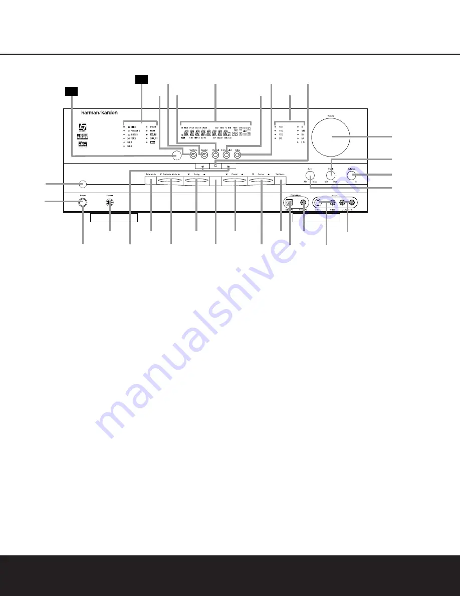
FRONT-PANEL CONTROLS
1
Main Power Switch
2
System Power Control
3
Power Indicator
4
Headphone Jack
5
Selector Buttons
6
Tone Mode
7
Surround Mode Selector
8
Tuning Selector
9
AM/FM Selector
)
Preset Stations Selector
!
Input Source Selector
@
Tuning Mode Selector
#
Digital Optical 3 Input
$
Digital Coax 3 Input
%
Video 3 Video Input Jacks
^
Video 3 Audio Input Jacks
&
Bass Control
*
Balance Control
(
Treble Control
Ó
Volume Control
Ô
Set Button
Input Indicators
Ò
Delay
Ú
Digital Input Selector
Û
Main Information Display
Ù
Channel Select Button
ı
Speaker Select Button
ˆ
Test Tone Selector
˜
Surround Mode Indicators
¯
Remote Sensor Window
AVR 125
AM/FM
dB
4
Ú
1
3
7
8
9
)
!
@
#
$
%
^
*
&
(
Ó
29
Û
Ô
2
6
30
Ò
ˆ
5
Ù
ı


