background image

6 - Ma

int

e

n

a

nc

e

6.15

If the shock absorbers loose their efficiency or start leaking oil, they should be replaced.

Sh

ock

 a

bsorb

e

rs

Wea

r


bus

h

in

r

epla

c

eme

nt


on


boo

m l

i

f

t

The wear bushings are inspected and replaced before they are worn
through.

1. Connect the trailer to a tractor and unfold the booms to working
position.

2. Lift the boom center frame with a lifting device and support it
until the load is taken off the parallelogram arms.

3. The upper arms must be disconnected simultaneously.

4. Remove the screws (A), and pull out the pins (B) for the upper par-
allelogram arms and replace the wear bushings (C).

5. Replace the arms.

6. Repeat this procedure with each of the lower arms.

7. Grease all grease nipples.

8. Remove the lifting gear again.

DANGER! Non observance of mounting instructions will result in the bad seating of the tire on the rim and could
cause the tire to burst leading to serious injury or death!

DANGER! Never mount or use damaged tires or rims! Use of damaged, ruptured, distorted, welded or brazed rim is
not allowed!

Should it be necessary to replace tires, it is recommended to leave this to a specialist and follow the mentioned rules.

1. Always clean and inspect the rim before mounting.

2. Always check that the rim diameter corresponds exactly to the rim diameter molded on the tire.

3. Always inspect inside of the tire for cuts, penetrating objects or other damages. Repairable damages should be
repaired before installing the tube. Tires with unrepairable damages must never be used.

4. Also inspect inside of the tire for dirt or foreign bodies and remove it before installing the tube.

5. Always use tubes of recommended size and in good condition. When fitting new tires always fit new tubes.

6. Before mounting, always lubricate both tire beads and rim flange with approved lubricating agent or equivalent anti-
corrosion lubricant. Never use petroleum based greases and oils because they may damage the tire. Using the appropri-
ate lubricant the tire will never slip on the rim.

7. Always use specialized tools as recommended by the tire supplier for mounting the tires.

8. Make sure that the tire is centered and the beads are perfectly seated on the rim. Otherwise danger of bead wire tear
can occur.

9. Inflate the tire to 15-19 p.s.i. (100-130 kPa) then check whether both beds are seated perfectly on the rim. If any of the
beads do not seat correctly, deflate the assembly and re-center the beads before starting inflation of the tire. If the beads
are seated correctly on the rim at 15-19 p.s.i., inflate the tire to a maximum of 36 p.s.i. (250 kPa) until they seat perfectly
on the rim.

10. Never exceed the maximum mounting pressure molded on the tire!

11. After mounting tires adjust inflation pressure to operation pressure recommended by the tire manufacturer.

12. Do not use tubes in tubeless tires.

Cha

n

ge 

o

tir

e

Summary of Contents for Ranger Series

Page 1: ...GLOBAL RANGER Instruction book 67021203 Version 1 00 US 07 2006 ...

Page 2: ......

Page 3: ...7021203 Version 1 00 US 07 2006 HARDI reserves the right to make changes in design material or specification without notice thereof HARDI and other product names are registered trademarks of HARDI Inc in the U S and in other countries ...

Page 4: ......

Page 5: ...al info MANIFOLD system 4 Pump 4 Valves and symbols 4 Green valves Green disc Pressure valve 5 Black valves Black disc Suction valve 5 Electrical operated MANIFOLD valves optional equipment 5 Diagram Diaphragm Liquid system 6 Diagram Centrifugal Liquid system 7 Control unit 7 Filters 7 CycloneFilter 8 HARDI FILLER 9 Agitation Tank Rinse valve 9 Boom 10 Boom and terminology 10 Equipment 11 Step opt...

Page 6: ...ystick control 2 Boom tilt function Joystick control 2 Maneuvering of the boom HZ version with DH control 3 Boom tilt function DH control 3 Folding one side only HZ Hydraulics only 4 Liquid system 5 Filling of water 5 Filling through tank lid 5 Suction filling device optional main tank only 6 Filling of main tank using Quick Fill optional 7 Filling of flush tank using Quick Fill optional 7 Filling...

Page 7: ...ral info 7 Pump valves and diaphragms replacement 7 Pump valves and diaphragms replacement 8 Cone check replacement for EVC operating unit 8 Cone check replacement for EVC distribution valve 9 Level indicator adjustment 9 Level indicator cord replacement 9 Drain valve seal replacement 10 Nozzle tubes and fittings 10 Adjustment of 3 way valve 10 Readjustment boom general info 11 Alignment of center...

Page 8: ...ragm pumps 2 Pump model 1303 9 0 2 Pump model 363 5 5 2 Pump model 363 10 0 2 Pump model 463 6 5 2 Pump model 463 12 0 2 Centrifugal pumps 2 Pump model ACE 206 hydraulic 2 Pump model ACE 150 PTO drive 2 Filters and nozzles 3 Temperature and pressure ranges 3 Tire pressure 3 Materials and recycling 3 Disposal of the sprayer 3 Electrical connections 4 Rear lights 4 Electrical connections for SPRAY I...

Page 9: ...growers There is no substitute for on farm experience and we invite your comments and suggestions If any portion of this instruction book remains unclear after reading it contact your HARDI dealer or service personnel for further explanation before using the equipment For Product Service or Warranty Information Please contact your local HARDI dealer To contact HARDI directly Please use the HARDI C...

Page 10: ...1 Welcome 1 2 ...

Page 11: ...Wash and change clothes after spraying Wash tools if they have become contaminated In case of poisoning immediately seek medical advice Remember to identify chemicals used Keep children away from the equipment If any portion of this instruction book remains unclear after reading it contact your HARDI dealer for further explanation before using the equipment Be careful not to hit people or surround...

Page 12: ...ter use and before servicing Do not attempt to enter the tank Do not go under any part of the sprayer unless it is secured The boom is secure when placed in the transport brackets If an arc welder is used on the equipment or anything connected to the equipment disconnect power leads before welding Remove all inflammable or explosive material from the area ...

Page 13: ...___ 3 _______________________________________________________________________________________________ 4 _______________________________________________________________________________________________ 5 _______________________________________________________________________________________________ 6 _______________________________________________________________________________________________ 7 __...

Page 14: ...2 Safety notes 2 4 ...

Page 15: ... 3 Spray pressure gauge 4 Pump 5 Hitch 6 Support jack 7 Suction filter 8 Step 9 Suction manifold 10 Quick Fill 11 Cyclone filter 12 HARDI FILLER 13 Flush tank 14 Pressure manifold 15 Clean water tank 16 Platform View General info 3 Description ...

Page 16: ...highway code applies or areas where there are special rules and regulations for marking and lights on implements you should observe these and equip implements accordingly Roadworthiness 18 Main tank 19 Foam marker compressor Frame boom center frame and other main steel components have identification plates indicating type and part number not illustrat ed An identification plate fitted on the frame...

Page 17: ...ery strong and compact frame which also has a strong chemical and weather resistant electrostatic powder coat Screws nuts etc have been DELTA MAGNI treated to be resistant to corrosion The main tank made of impact proof UV resistant and chemical resistant polyethylene has a purposeful design with no sharp corners for easy cleaning Nominal contents 600 gal 2200 liters A large easy to read tank cont...

Page 18: ...6 hydraulic or 150 PTO Standard 540 r p m 6 splines Optional 1000 r p m 20 or 21 splines The valves at the MANIFOLD are distinguished by colored identification discs on the valves Symbols corresponding to every possible function of use are located on the discs for easy identification and operation A function is activated by turning the handle towards the desired function Valves and symbols Pump Ge...

Page 19: ...of liquid that passes through the valve This allows for a continuously variable flow to agitation or tank rinsing To HARDI FILLER To Agitation To Tank Rinsing Nozzle Green valves Green disc Pressure valve From main tank From flush tank From Quick Fill Black valves Black disc Suction valve The position of the suction manifold valves determine the source of the liquid When the arrow on the handle is...

Page 20: ... 5 Agitation 6 Safety valve 7 HARDI MATIC 8 Cyclone filter optional 9 Off On Purge valve Diagram Diaphragm Liquid system 10 Check valves 11 Boom section valves 12 Boom 13 Flush tank optional 14 Quick fill optional 15 HARDI FILLER optional 16 Tank rinse nozzle optional 17 Boom pressure gauge ...

Page 21: ...n HARDI MATIC 9 Check valve 10 Boom section valves 11 Boom 12 Flush tank optional 13 Quick fill optional 14 HARDI FILLER optional 15 Tank rinse nozzle optional 16 Boom pressure gauge Control unit Diagram Centrifugal Liquid system Nozzle filters are fitted at each nozzle In line pressure filters can be fitted at each section as an option A suction filter can also be fitted under the platform All fi...

Page 22: ...k 5 Return valve Valve 5 has three positions marked with small dots on the lever Position A Marked with 1 dot There is no return flow Position is used when flushing the boom if there is spray liquid in the main tank Also used when high spraying volume is required Position B Marked with 2 dots Normal spraying position With return flow to prevent clogging the filter when spraying Position is used wh...

Page 23: ...If handle is turned to a position near the tip of the arrow then only a small amount of liquid is allowed to pass the valve Otherwise if handle is turned to a position in the wide end of the arrow it means that a larger amount is passing the valve This gives the possibility to continuously adjust how much fluid from the pump is used for agitation rinsing in the tank Examples on handle positions at...

Page 24: ...for boom height adjustment and two cylinders for simultaneous boom wing fold and unfold 2 SPB HZ This type of boom has the same features as the above mentioned HY model but is provided with more advanced hydraulics SPB HZ also has two boom wing tilt cylinders that give the ability to obtain individual boom wing tilt as well as individual boom wing fold The hydraulics on the SPB HZ are controlled v...

Page 25: ...water tank lid the main tank lid and the optional foam marker tank lid The actual tank level in the main tank can be observed on the tank level indicator The scale is displayed in US gallons or Liters Tank level indicator Platform The optional platform step is located on the left side of the sprayer frame to make it easier to climb up to the platform Step optional ...

Page 26: ...the platform This gauge measures the working pressure in the boom tubes as close to the nozzles as possible The outputs stated in the nozzle charts are always based on the pressure measured at the nozzle Always adjust pressure when cali brating and spraying according to readings at the remote pressure gauge ...

Page 27: ...SIS FLUID on all metal parts in order to avoid chemicals and fertilizers discoloring the enamel If this is done before the sprayer is put into opera tion for the first time it will always be easy to clean the sprayer and keep the enamel clean for many years This treatment should be carried out every time the protection film is washed off Support jack The support jack is stored in retracted positio...

Page 28: ...cient slack for turns 6 Make sure that protection guards around tractor P T O and implement shaft are intact 7 Always STOP ENGINE and remove the ignition key before carrying out maintenance or repairs to the transmission shaft or implement Adjusting the height of the hitch is obtained by removing the four bolts A and raising or lowering the hitch Inverting the hitch will allow for a greater adjust...

Page 29: ...ins to prevent the protection guards from rotating with the shaft 8 To ensure long life of the transmission shaft try to avoid working angles greater than 15 4 The two parts are shortened equally Use a saw and file the pro files afterwards to remove burrs 5 Grease the profiles and assemble male and female parts again 6 Fit the shaft to tractor P T O and sprayer pump shaft ATTENTION Female part mar...

Page 30: ...c systems Connection requirements are One single acting hydraulic outlet for the lift function of the spray boom Two double acting hydraulic outlets for the folding function of the sprayer Ensure that snap couplers are clean before connection The hydraulic system requires an oil flow of approximately 0 8 GPM 3 liters and a minimum pressure of 1 950 PSI 130 bar Requirements tractor SPB HY SPB HZ WA...

Page 31: ...ch the wires to the actual tractor connector Control boxes are fitted in the tractor cabin at a convenient place The supplied tractor pillar bracket A has a hole spacing of 3 9 in 100mm and 4 7 in 120mm Check tractor instructions manual for information regarding attachment points Three tubes B are supplied One two or all 3 may be used They can be bent and shortened A spacer C is also supplied to a...

Page 32: ...ydraulic control box B in a suitable location in the tractor cabin 4 Connect the female 7 pin plug C from the switch box to the 7 pin male plug D from the sprayer Installation of handle is done as follows 1 Attach the control handle joystick A to the hydraulic lever that operates the double acting outlet to be used The universal mount ing bracket B is very flexible and a number of different mounti...

Page 33: ...accordance with ISO 1724 See section in Technical specifications Road safety kit Find a suitable place in the tractor s cabin Best recommended placement is to the right of the driver seat and in combination with the Hydraulics control unit It should be secured from movement Installation of control box EVC control unit ATTENTION Tractor driver s seat is the intended working place during operation ...

Page 34: ...rack width center RH tire to center LH tire Each side must be extended or retracted half the desired alteration 2 Attach the sprayer to tractor and engage tractor parking brake 3 Place stop wedges in front of and behind RH wheel Jack up frame behind LH wheel support and secure sprayer body 4 Remove bolts A for LH axle insert 5 Extend or retract the axle 6 Replace bolts A and tighten to specified t...

Page 35: ...ulic outlet to raise the boom and release it from the transport brackets 2 Activate the double acting hydraulic outlet to unfold the boom Both wings will now unfold simultaneously 3 When the boom is completely unfolded it can be raised or lowered to the desired spray height by activating the single acting hydraulic outlet 4 Before attempting to fold the boom back into transport position it must be...

Page 36: ...ow unfold simultaneously 3 One side folding will be achieved by following step 2 except that only one of the switches is depressed See section Folding one side only 4 When the boom is completely unfolded it can be raised or low ered to the desired spray height by activating the single acting hydraulic outlet 5 Before attempting to fold the boom back into transport position it must be raised all th...

Page 37: ...4 One side folding will be achieved by following step 3 except that only one of the switches is activated See section Folding one side only 5 When the boom is completely unfolded it can be raised or low ered to the desired spray height by activating the single acting hydraulic outlet 6 Before attempting to fold the boom back into transport position it must be raised all the way to the top by activ...

Page 38: ...nd then turn switches off Then activate the switch for the side that is to be folded and activate the double acting outlet to fold that side into transport position ATTENTION It is not advisable to go directly from transport position to spray position with one side only Both wings must first be completely unfolded and then one side folded back in ...

Page 39: ...upply lines and source Tank should normally be filled 1 3 with water before adding chemi cals Always follow instructions given on the chemical container Water is filled into the tank by removing the tank lid located at front of sprayer tank which is accessible from platform It is recommended to use water as clean as possible for spraying purposes Always fill water through the strainer basket to pr...

Page 40: ...quipped Otherwise turn to Spray with control unit turned Off 4 Engage pump and set to operating r p m 540 1000 5 Turn top Suction Manifold valve towards Quick Fill function 6 Water will be drawn from the water supply Fill tank to desired level Keep an eye on the level indicator 7 Chemicals may be added to the HARDI FILLER optional while using the suction filling device Follow directions in section...

Page 41: ...level Be careful not to overfill 6 Turn top Suction Manifold valve Off to discontinue filling process 7 Turn water supply Off and remove the filling hose 8 Replace Quick Fill plug Capacity 66 gal 250 liters Only fill flush tank with clean water To avoid algae developing in the flush tank always drain the flush tank if the sprayer is not in use for a longer period of time For cleaning purposes etc ...

Page 42: ... the pressure gauge This reading will be used throughout the adjustment 3 Manually close one of the distribution valves by turning the green handle A 4 Turn the adjusting screw B under the valve just closed until the pressure gauge again shows the same pressure as before clockwise for higher pressure counterclockwise for lower pressure 5 Turn the distribution valve A back on 6 Adjust the other sec...

Page 43: ...manufacturer s instructions given on the chemical label WARNING It is always advisable to have clean water available especially when filling the sprayer with the chemi cal WARNING Always clean the sprayer carefully and immediately after use WARNING Only mix chemicals in the tank according to directions given by the chemical manufacturer WARNING Always clean the sprayer before changing to another c...

Page 44: ...e Manifold valve handle towards Spray and the bottom Pressure Maniflold valve towards Agitation 3 Engage pump and set to operating r p m 540 1000 4 Add the chemicals through the main tank hole 5 When the spray liquid is well mixed keep P T O engaged so the spray liquid is continuously agitated until it has been sprayed on the crop The chemicals are filled through the tank lid Note instructions on ...

Page 45: ...ling of water 2 Turn the handle at the bottom Suction Manifold towards Main tank Turn top Pressure Manifold valve towards HARDI FILLER and the bot tom Pressure Manifold valve towards Agitation Close remaining valves 3 Check that bottom valve A at the FILLER is closed 4 Engage pump and set to operating r p m 540 1000 5 Open FILLER lid 6 Measure the correct quantity of chemical and fill it into the ...

Page 46: ...e is stated on the chemical container label See section Filling of water 2 Turn the handle at the bottom Suction Manifold towards Main tank Turn top Pressure Manifold valve towards HARDI FILLER and the bot tom Pressure Manifold valve towards Agitation 3 Engage pump and set to operating r p m 540 1000 4 Open the bottom valve A at the FILLER Open FILLER lid 5 Engage the hopper rinsing device by open...

Page 47: ... the sections which are to remain open On the sprayer the bottom Suction Manifold valve should be turned toward Suction from Main tank The top Pressure Manifold valve should be turned toward Spraying and the bottom Pressure Manifold valve to Agitation if necessary If a spraying job has been interrupted for a while severe sedimenta tion can occur depending on chemicals being used When re start ing ...

Page 48: ...5 Operation 5 14 In the following diagram valve positions for different options are described Quick reference Operation ...

Page 49: ...n a soakaway This is an area of ground that is not used for cropping You must avoid seepage or runoff of residue into streams water courses ditches wells springs etc The washings from the cleaning area must not enter sewers Drainage must lead to an approved soakaway 4 Cleaning starts with the calibration as a well calibrated sprayer will ensure the minimal amount of remaining spray liq uid 5 It is...

Page 50: ... completely filled Add appropriate detergent and or deactivating agent e g washing soda or Triple ammonia 7 Start the pump and operate all controls enabling the liquid to come in contact with all the components Leave the dis tribution valves until last Some detergents and deactivating agents work best if left in the tank for a short period Check the label The Cyclone filter can be flushed by engag...

Page 51: ... bottom valve 5 Turn the top Pressure Manifold Valve towards Spray and spray liquid in the field you have just sprayed Cleaning of Main tank 6 Turn the Suction valve towards Flush tank and bottom Pressure valve towards Tank Rinsing 7 When another 1 4 of contents in flush tank are used then turn Suction valve towards suction from Main tank and bottom Pressure valve Off no agitation 8 Turn top Press...

Page 52: ...an water and sprayed onto the crop just sprayed before cleaning the sprayer Technical residue Quick reference Cleaning The drain valve is located and operated from the left hand side of the sprayer near the boom transport bracket Pull the string to open the drain valve The valve is spring loaded but can be kept open by pulling the string upwards in the V shaped slit To release pull the string down...

Page 53: ...id skin con tact with oil products for longer periods Always follow the shown direction concerning recommended quan tity If no recommended quantity is given feed lubricator until new grease becomes visible Pictograms in lubrication oiling plans tell the following 1 Lubricant to be used see Recommended lubricants 2 Operating hours before next lubrication SLIDE BEARINGS Lithium grease with Molybdenu...

Page 54: ...6 Maintenance 6 2 Trailer lubrication oiling plan ...

Page 55: ...ways be turned to the unused position before opening the Cyclone filter If not then spraying liquid can hit you when opening the filter and drain from the tank To service the Cyclone filter 1 Turn top Pressure Manifold valve Off 2 Unscrew filter lid A 3 Lift the lid and filter B from housing 4 Separate filter from the integrated filter guide in the lid and clean the filter To reassemble 1 Grease t...

Page 56: ...uit 10 hours service Nozzle filters Tighten wheel bolts and nuts as follows with following torque wrench settings Wheel hub to rim plate 160 Ft lb 215 Nm Tightening sequence See illustration and tighten in order of num bering 50 hours service Wheel bolts and nuts If the boom is equipped with In Line Filters unscrew the filter bowl to inspect and clean the filter When reassembling the O ring should...

Page 57: ...astle nut until the first notch horizontal or vertical is aligned with the cotter pin hole in the shaft 6 Fit a new cotter pin and bend it 7 Fill the hub cap with fresh grease and screw it on to the hub again 8 Repeat the procedure on LH wheel 250 hours service Wheel bearings 250 hours service Hoses and tubes 250 hours service Hydraulic circuit 250 hours service Readjustment of the boom Change the...

Page 58: ...aling ring E 9 Fit castle nut Rotate hub and tighten castle nut until a slight rota tion resistance is felt 10 Loosen castle nut again until the first notch is aligned with the cotter pin hole in the shaft 11 Fit a new cotter pin and bend it 12 Fill the hub cap with fresh grease and carefully press it onto the hub 13 Replace the wheel and tighten the wheel nuts See 50 hours service Wheel bolts and...

Page 59: ...possible to specify Diaphragms Remove the diaphragm bolt 4 The diaphragm 5 may then be changed If fluids have reached the crankcase re grease the pump thoroughly Also check that the drain hole at the bottom of the pump is not blocked Reassemble pump model 363 463 with the following torque setting 463 Diaphragm cover 65 Ft lb 90 Nm 463 Diaphragm bolt 60 Ft lb 80 Nm 363 Diaphragm cover 50 Ft lb 70 N...

Page 60: ...agm pump overhaul kit valves seals diaphragms etc can be ordered Model 1303 part No 750658 Valves Remove valve cover 1 Before changing the valves 2 note their orientation so they are replaced correctly It is recommended to use new O rings 3 when changing or checking valves Diaphragms Remove the diaphragm cover 4 Remove the diaphragm bolt The diaphragm 5 may then be changed If fluids have reached t...

Page 61: ...ty the float should lie on the stop pin of the rod and the O ring on the indicator should be positioned at the top position line A If any deviation is found pull out the plug B loosen screws C and adjust the length of the cord Level indicator adjustment Cone check replacement for EVC distribution valve DANGER Do not enter the inside of the tank the parts can be changed from the outside of the tank...

Page 62: ...rmed O rings or gaskets Foreign bodies The MANIFOLD valve can be adjusted if it is too tight to operate or if it is too loose liquid leakage Correct setting is when the valve can be operated smoothly by one hand Use a suitable tool and adjust the toothed ring inside the valve as shown on the drawing Adjustment of 3 way valve DANGER Do not enter the inside of the tank the parts can be changed from ...

Page 63: ...n jam nut B and adjust the length of the rod eye A IN to move the boom forward OUT to move the boom rearward 5 Tighten the jam nut B again Reattach the cylinder rod to the boom again if it has been loosened 6 Pressurize the cylinder to check boom alignment Alignment of center and inner wing sections Readjustment boom general info 1 Unfold the boom and check that the boom wing is aligned If adjustm...

Page 64: ...s E on the turnbuckle assembly and adjust turn buckle F for proper cable deflection 6 Tighten jam nuts E again and remove weight WARNING Check boom alignment again If front cable was tightened the wing assembly will move a bit forward If front cable was loosened the wing assembly will move a bit rear ward Therefore adjust fold cylinder if necessary as described in the section Alignment of center s...

Page 65: ...ck that the boom sections are parallel to the center frame and level to the ground Adjust if necessary as described below Adjustment is carried out with the boom unfolded For SPB HY models the following procedure is used 1 Loosen jam nut A 2 Adjust nut B in or out until boom wing is level to the ground 3 Secure jam nut A again Same procedure applies to both sides Adjusting boom level to ground For...

Page 66: ...e tension and maintain a level center frame WARNING Never adjust the center cables without having folded the boom all the way into the transport position The center section cables keep the center frame in correct position during folding procedure or when spraying with one side raised and folded SPB HZ only 1 Fold the boom into transport position 2 Check that the tilt cylinders are completely exten...

Page 67: ...ct inside of the tire for cuts penetrating objects or other damages Repairable damages should be repaired before installing the tube Tires with unrepairable damages must never be used 4 Also inspect inside of the tire for dirt or foreign bodies and remove it before installing the tube 5 Always use tubes of recommended size and in good condition When fitting new tires always fit new tubes 6 Before ...

Page 68: ... mandrel if necessary 4 Remove needle bearing cups and cross journal can now be removed 5 Carefully remove needle bearing cups from new cross journal and install it in reverse order Before fitting the needle bearing cups again check that needles is placed correctly Avoid dust and dirt in the new bearings 6 Repeat procedure to the opposite part of the transmission shaft Replacement of transmission ...

Page 69: ...sting of 1 3 automotive anti freeze and 2 3 water into the tank 5 Engage the pump and operate all valves and functions on the MANIFOLD operating unit chemical inductor etc allow ing the anti freeze mixture to be distributed around the entire circuit Open the operating unit main on off valve and dis tribution valves so the anti freeze is sprayed through the nozzles as well The anti freeze will also...

Page 70: ...6 Maintenance 6 18 ...

Page 71: ...tightly against the valve seat This reduces pump efficiency 5 Poorly reassembled pumps especially diaphragm covers will allow the pump to suck air resulting in reduced or no capacity 6 Hydraulic components that are contaminated with dirt result in rapid wear to the hydraulic system Therefore ALWAYS check 1 Suction pressure and nozzle filters are clean 2 Hoses for leaks and cracks paying particular...

Page 72: ...ctioning FAULT Air in system Centrifugal pump Pump valves blocked or worn Nozzles worn Excessive liquid agitation Wrong polarity Bleed air from centrifugal pump Check for obstructions and wear Check flow rate and replace nozzles if it exceeds 10 Reduce pump r p m Check safety valve is tight diaphragm systems only Ensure returns inside tank are present Use foam damping additive Brown pos Blue neg S...

Page 73: ...heck clean connections multi plugs etc Hydraulic system HZ model CONTROL REMEDY Air in system Restrictor blocked PROBABLE CAUSE Loosen ram connection and activate hydraulics until oil flow has no air in it not whitish Secure boom Dismantle and clean Change hydraulic oil fil ter Boom slow erratic Ram not functioning FAULT Insufficient hydraulic pressure Check output pressure of tractor hydraulics M...

Page 74: ...d block Check for a solenoid that is stuck open Boom will not fold in or out Boom will not fold completely Boom not aligned Boom will not stay in spraying position Wing to be kept folded swings out when unfolding other side of the boom FAULT In case of power failure it is possible to operate all functions of the operating unit manually First disconnect the multi plug from the control box Now manua...

Page 75: ...rs Foam marker tank capacity 10 15 or 20 gallons 38 57 or 76 Liters Specifications Total Drawbar Axle Per tire Unfolded empty 1574 39 1535 768 Folded empty 1574 163 1411 705 Unfolded full water 4449 831 3618 1809 Folded full water 4449 955 3494 1747 All measurements are in pounds Weight Wheel Min track width Max track width Clearance 12 4x24 60 1520mm 90 2250 mm 18 460 mm 13 6x38 60 1520mm 90 2250...

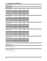
Page 76: ...l 363 10 0 PSI RPM GPM HP 0 540 51 2 2 4 29 540 49 9 3 1 58 540 49 1 3 9 88 540 48 6 4 6 147 540 48 0 6 4 220 540 47 0 8 4 Pump model 463 6 5 PSI RPM GPM HP 0 1000 91 9 4 3 29 1000 84 8 5 4 58 1000 82 7 6 8 88 1000 81 4 8 3 147 1000 78 2 11 0 220 1000 75 5 13 8 Pump model 463 12 0 PSI RPM GPM HP 0 540 85 0 3 0 29 540 83 7 4 2 58 540 82 9 5 6 88 540 81 3 6 9 147 540 79 7 9 5 220 540 77 9 9 9 Output...

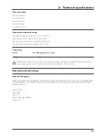
Page 77: ...GER Never inflate tires more than to the pressure specified in the table Over inflated tires can explode and cause severe personal injuries See the part Occasional maintenance Change of tire Temperature and pressure ranges Filters and nozzles When the equipment has completed its working life it must be thoroughly cleaned The tank hose and synthetic fittings can be incinerated at an authorized disp...

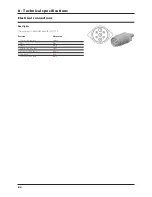
Page 78: ...olor 1 LH direction indicator Yellow 2 Free Blue 3 Frame White 4 RH direction indicator Green 5 RH rear position lamp Brown 6 Stop lamps Red 7 LH rear position lamp Black The wiring is in accordance with ISO 1724 Rear lights Electrical connections ...

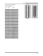
Page 79: ... S7 7b 19 S7 7c 33 Option 1 4 20mA 8a 37 S8 8b 36 S8 8c 32 Option 2 Frq 9a 35 S9 Air angle 0 5V 9b 34 S9 Fan speed 0 5V 9c not connected Option 3 Tank gauge 10a 21 On off 10b 22 On off 10c not connected PWM Output option 11a 23 Pressure 11b 24 Pressure 11c 28 Flow 12a 20 Foam blop 0 5V 12b 1 option 4 Rx 12c 31 Speed 13a 3 FM L 13b 2 FM R 13c 30 Gnd sensor 39 pole 37 pole SPRAY II 39 or 37 poled pl...

Page 80: ...6 The EVC operating unit fulfills the EC noise reduction standards When connecting an optional function be aware that maximum current for every connector is 2 Amp Total current for the whole connector box may not exceed 10 Amp EVC ...

Page 81: ...lu Sec 3 Brn Blu Sec 2 Brn Blu Sec 1 Brn Blu Gnd L R Foam marker No 4 Not used 2 6 5 1 3 HC 2500 Function Sig Opt 1 Pressure sensor Brn Blu Opt 2 RPM sensor or anemometer Brn Blu Blk Speed Brn Blu Blk Flow Brn Blu Blk L end nozzle Pendulum lock at HAY LPY Brn Blu R endnozzle Pendulum lock at HAY LPY Brn Blu Reg Yellow Brn Blu Bypass EC on off Brn Blu Sec 9 User defined A B 2 x x Sec 8 User defined...

Page 82: ...8 Technical specifications 8 8 Boom hydraulics HZ Boom hydraulics HY Charts ...

Page 83: ...8 Technical specifications 8 9 Boom hydraulics DH ...

Page 84: ...8 Technical specifications 8 10 ...

Page 85: ...he owner or to a third party nor can we be called upon to be responsible for labor charges other than originally agreed incurred in the removal or replacement of components 3 The customer will be responsible for and bear the costs of a Normal maintenance such as greasing maintenance of oil levels minor adjustments etc b Transportation of any HARDI product to and from where the warranty work is per...

Page 86: ...ms under this warranty shall be final and conclusive and the purchaser agrees to accept its decisions on all questions as to defect and to the exchange of any part or parts 12 No employee or representative is authorized to change this warranty in any way or grant any other warranty unless such change is made in writing and signed by an officer of HARDI at it s head office 13 Any warranty work perf...

Page 87: ......

Page 88: ...1 4160 337 Sovereign Rd London Ontario N6M 1A6 Phone 519 659 2771 Fax 519 659 2821 For Product Service or Warranty Information Please contact your local HARDI dealer To contact HARDI directly Please use the HARDI Customer Service number 1 866 770 7063 Or send your email to CUSTSERV hardi us com HARDI NORTH AMERICA INC Visit us online at www hardi us com ...

Reviews: