Hardi HC 6500 Instruction Book Download Page 35

6.1

6 - Menu 2 Setup

Menu 2.1 Display readout

General info 

The following menu explanations assume you have mastered the general keystrokes and you can “find your way” to the 
specific menu. If this is not so, please re-read section “Keys”. 

Menu 2.1.1 Display readout 

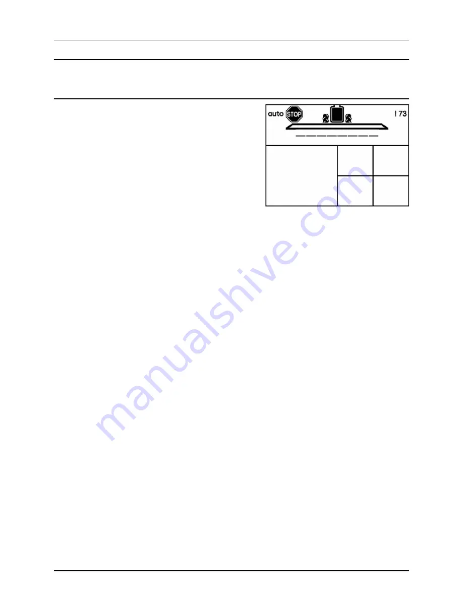
It is possible to choose which functions are shown in the 4 different 
boxes (A, B, C and D) of the display. 

1.

Go to menu [2.1 Display readout]. 

2.

Use ¿ or ª to choose which of following boxes you want the 
data shown in and press # to confirm. 
2.1.1 Show upper middle (A) 
2.1.2 Show upper right (B) 
2.1.3 Show lower middle (C)
2.1.4 Show lower right (D) 

3.

Choose a submenu e.g. menu [2.1.1.04 Work rate]. Press # to 
confirm. 

4.

Press ~ to leave menu. 

See next page for a complete list of possible display readouts. 

A

B

C

D

Summary of Contents for HC 6500

Page 1: ...CONTROLLER HC6500 Instruction book sw 1 2x 67021903 Version 1 20 US 08 2010 ...

Page 2: ......

Page 3: ...1 2X 67021903 Version 1 20 US 08 2010 HARDI reserves the right to make changes in design material or specification without notice thereof HARDI and other product names are registered trademarks of HARDI Inc in the U S and in other countries ...

Page 4: ......

Page 5: ... General keystrokes Example Tank contents 9 Keystroke menu tree 9 Extended menu 9 Auto functions 10 General info 10 End nozzles Fence line optional 10 TWIN Preset 10 HARDI AutoSectionControl 10 4 System setup Tractor installation 1 Control units 1 Installation of control unit brackets 1 Power supply 2 Mounting of tractor harness 2 Printer 2 Speed transducer for sprayer 3 Speed transducer for tract...

Page 6: ...not used in North America 4 Menu 2 3 VRA Remote control 5 Variable Rate Application VRA Remote HARDI AutoSectionControl 5 Menu 2 4 Set clock 6 How to set clock 6 Menu 2 5 Alarms Warnings and Info 7 How to set up alarms 7 Warnings 7 Menu 2 6 Register names 8 How to name the registers 8 7 Menu 3 Calibration Menu 3 1 Speed calibration 1 Menu 3 1 1 Sprayer 1 Menu 3 1 1 1 Constant 2 Menu 3 1 1 2 1 Prac...

Page 7: ...ervice interval reset 3 Service interval reset 3 Menu 4 4 Reserved 4 Reserved function This menu is not used 4 Menu 4 5 Test 5 How to test 5 Menu 4 6 Speed simulation 6 How to use speed simulation 6 Menu 4 7 Emergency Track 7 Menu 4 7 Emergency Track 7 Menu 4 8 Computer CAN status 8 Menu 4 8 X Computer CAN status 8 9 Menu 5 Logbook Menu 5 1 Print 1 What you can print 1 Menu 5 2 Data dump 2 How to ...

Page 8: ...ransducer 1 Testing speed transducer 2 14 Technical specifications Specifications 1 Specifications 1 Flow ranges for the flow transducers 1 Electrical connections 2 Types of plugs and fuses 2 Materials and recycling 3 Disposal of electronics 3 Packaging information 3 Charts 4 Chart for recording values 4 15 Warranty Warranty policy and conditions 1 ...

Page 9: ...n Some of the features on your HARDI controller were suggested by growers There is no substitute for on farm experience and we invite your comments and suggestions If any portion of this instruction book remains unclear after reading it contact your HARDI dealer or service personnel for further explanation before using the equipment For Product Service or Warranty Information Please contact your l...

Page 10: ...1 Welcome 1 2 ...

Page 11: ...his book Keep children away from the equipment If any portion of this instruction book remains unclear after reading it contact your HARDI dealer for further explanation before using the equipment Turn electrical power off before connecting and disconnecting the display and transducers servicing or using a battery charger If an arc welder is used on the equipment or anything connected to the equip...

Page 12: ...___________________________________ 3 _______________________________________________________________________________________________ 4 _______________________________________________________________________________________________ 5 _______________________________________________________________________________________________ 6 ____________________________________________________________________...

Page 13: ...adout is possible even for night time work Functions include correct area with closure of up to 13 spray boom sections up to 27 alarm functions and the possibility for audio visual alarm etc There are also 23 warnings depending on operation Alarms and warnings will be shown in the bottom left corner of the display The Grip has integrated controls for the spray functions up to 13 sections main ON O...

Page 14: ... and application rate will be used This is selected from a number of nozzle choices stored in memory At start up of the controller it will prompt user for a choice between using nozzles from last spray job or selecting a new nozzle to be used μ ATTENTION The tractor gearbox must be an automatic or semi automatic type with constant revolutions P T O or the tractor must be driven with constant R P M...

Page 15: ...dth Tire pressure Read sprayer s instruction book for further information If unsafe driving occurs an alarm will be triggered and the sprayer will align Be aware that the alarm cannot be turned off as long as unsafe driving still occurs See paragraph Menu 3 6 Track μ ATTENTION If necessary the level of security can be adjusted please contact your local HARDI dealer DANGER The system has been calib...

Page 16: ... 4 HC 6100 Jobcom junction box 5 Harness for the tractor 6 Harness for the cabin 7 Harness for the sprayer 8 Speed sensor pulse ring 9 Flow sensor 10 Power supply to sprayer 11 Hydraulics block 12 EFC junction box 13 Electric Fluid Control unit 14 LookAhead pressure control 15 LookAhead boom position sensor ...

Page 17: ... can change the volume rate in a set percentage or fixed volume rate is used to clear a value or register is used to escape back to your working screen Is used if you have questions about the menu you are in A short help text will appear D Numeric keys These are very much like a mobile phone It is very easy to enter text like a field name They are also used to key in a value or directly access a m...

Page 18: ...llumination Go to menu 2 7 1 Choose day night colors for selection Picture shows night illumination Volume rate Automatic Warning Track Crab right Option B on Pendulum Locked Volume rate Manual Information TWIN Manual Options both on Pendulum Unlocked Variable rate GPS active Track Automatic TWIN Preset 1 Not used in North America Not used in North America All OK Track Manual TWIN Preset 2 Not use...

Page 19: ...2 Valve function A B 13 Not used in North America 14 Not used in North America 15 Not used in North America 16 SafeTrack manual control 17 SafeTrack align 18 SafeTrack automatic selection Grip HC 6300 The Grip is an ergonomic remote unit that can be easily mounted inside the tractor cabin All common functions required during normal spraying can be operated with the Grip The Grip cannot be switched...

Page 20: ...or page When adjustments are made in settings the display will be as shown The two markings show the actual menu where you are located It is now possible to go up and down by using the and ª keys or by pressing the menus last digit at the numeric keypad e g pressing 6 for menu 4 6 Speed simulation The last value which was used is marked with this symbol In the bottom of the display there will be h...

Page 21: ... choose a menu are shown below Press to proceed into the menu See the relevant section in the book Press and hold to exit the menu system Extended menu This menu has been set up by your HARDI Service center It contains parameters that are typically set only once normally before the Controller is used μ ATTENTION Unless instructed do not tamper with the settings and values in these menus Doing so m...

Page 22: ...is displayed it will show an increase when the end nozzle or Bijet is activated TWIN Preset It is possible to set the air volume and air angle in 2 different positions in menu 2 2 5 to 2 2 5 2 for headwind and tailwind When air volume and air angle are set a long key press position 1 headwind will store the present setting The same setting can be done for position 2 tailwind TWIN preset can be set...

Page 23: ... manual for information regarding attachment points Three tubes B are supplied One two or all 3 may be used They can be bent and shortened A spacer C is also supplied to allow further attachment possibilities Find the best solution for your tractor or vehicle Tube B plate is staggered so all boxes will line up if correctly oriented The recommended setup is to place the spacer C between the two tub...

Page 24: ...r generator alternator Warranty is void if this is done μ ATTENTION See paragraph System start up for more about connecting the controller Mounting of tractor harness Mount fuse on pole at tractor battery Connections are as follows A Red B Red Brown C Yellow D Mounted on pole at tractor battery E Black F Black White G Blue H Mounted on pole at tractor battery WARNING Connector H must be connected ...

Page 25: ...ucer when the wheel rotates Speed transducer for tractor It is possible to connect a speed sensor from tractor gearbox or radar GPS to the controller A speed switch harness A and extension cable are needed to connect the speed transducer to the Controller Terminal Foot pedal remote ON OFF optional Note the following if the Foot pedal remote is to be fitted Remote ON OFF switch has to be activated ...

Page 26: ... control unit 1 Terminal HC 6500 2 SetBox HC 6400 3 Grip HC 6300 4 To Jobcom HC 6100 on sprayer 5 Printer connection DB 9 COM1 COM2 port 6 DB 25 connector harness with power and CAN communication 7 Tractor harness 8 Connector for tractor to Jobcom HC 6100 9 Power from tractor battery with a 25 amp fuse ...

Page 27: ...t up of the controller The present selected nozzle is designated by the symbol at the line of the nozzle description in the display If the nozzle used at last spray job is going to be re used then press or Selecting another nozzle 1 Select another nozzle by pressing or ª 2 Confirm the choice by pressing If LookAhead is not calibrated then the screen changes to menu 3 7 1 1 Application rate Enter t...

Page 28: ...ter pressure regulation valve is stable i e does not rotate adjust wait 30 seconds before proceeding 7 Press main ON OFF at the grip to OFF to close all sections 8 Go to menu 4 6 speed simulation Key in e g 6 mph and press to use the value Check if pressure regulation valve rotates counterclockwise to reduce pressure immediately after pressing If pressure regulation valve rotates when all sections...

Page 29: ...he symbol at the line of the nozzle description in the display If the nozzle and application rate used at last spray job is going to be re used then press and the work screen will appear If another nozzle will be used then confirm your nozzle selection by pressing Then the minimum pressure screen will appear If LookAhead is enabled then LookAhead calibration will be done before menu E8 1 3 Minimum...

Page 30: ...4 System setup 4 8 ...

Page 31: ...ld until menu 1 1 VOLUME RATE is shown To change volume rate Move cursor with or to the value to be changed Use or ª to change the value Alternatively clear value by pressing and key in value on the numeric keys Press to confirm Manual dosage To dose in manual mode use the pressure buttons on the SetBox HC 6400 The manual mode is indicated by the symbol at the top of the display To go from manual ...

Page 32: ...ve the cursor in order to change the value Press or ª to set the desired value Press to confirm The maximum size of the tank is displayed Press again and the tank contents maximum value is shown μ ATTENTION If the sprayer is fitted with Tank gauge contents readout is automatic 1 2 Tank cont 0 gallon To change displayed tank contents Use arrow or numeric keys to set ...

Page 33: ... 3 Press again to see spray data 4 Press to exit the menu To change the register Shortcut 1 Press and hold until menu 1 3 Select register is shown 2 Press or ª to change the register 3 Press If necessary the register can be reset see below 4 Press to exit the menu To reset register Press and hold for 5 seconds to reset register Status diode will blink once and then blink again to indicate that reg...

Page 34: ...to select another nozzle without re starting the controller Do the following 1 Go to menu 1 6 LookAhead nozzle select then press 2 Select nozzle with or ª 3 Confirm by pressing 4 The Controller jumps to menu 3 7 1 1 Application rate Enter an application rate here 5 See further steps in the chapter Menu 3 7 LookAhead ...

Page 35: ...to choose which functions are shown in the 4 different boxes A B C and D of the display 1 Go to menu 2 1 Display readout 2 Use or ª to choose which of following boxes you want the data shown in and press to confirm 2 1 1 Show upper middle A 2 1 2 Show upper right B 2 1 3 Show lower middle C 2 1 4 Show lower right D 3 Choose a submenu e g menu 2 1 1 04 Work rate Press to confirm 4 Press to leave me...

Page 36: ...ive boom size including End nozzle 2 1 1 11 Pressure Displays spray pressure if sensor is fitted 2 1 1 12 Fan speed Displays Twin fan speed if sensor is fitted 2 1 1 13 Wind speed Displays wind speed if sensor is fitted 2 1 1 14 Wind direction Displays wind direction if sensor is fitted 2 1 1 15 Humidity Displays relative humidity if sensor is fitted 2 1 1 16 Temperature Displays ambient temperatu...

Page 37: ...to set the main ON OFF switch to OFF before leaving the field otherwise the main ON OFF will open under transport Menu 2 2 2 Foam Marker optional The Controller can be set to operate the HARDI Foam marker automatically through the main ON OFF valve When the main ON OFF is ON it will automatically start the Foam marker Furthermore the Foam marker can be set for up and back spraying or race track ro...

Page 38: ...in ON OFF or manually at key press Select the way to use the function in the submenus Menu 2 2 5 1 selects whether manual operation is done at the HC 6400 or at the buttons behind the grip Menu 2 2 5 2 is for selecting of automatic shift every time the main ON OFF is pressed Menu 2 2 5 3 disables the function Menu 2 2 6 AutoAgitation select level not used in North America This menu is not used in ...

Page 39: ...sible Manual pressure regulation and stepped over under application is still possible The external source is connected to the COM 1 or COM 2 via a 9 pin sub D connector ATTENTION The COM port may have to be set up in the extended menu Contact your HARDI service center μ ATTENTION Use of HARDI AutoSectionControl requires a sprayer equipped with JobCom computer If in doubt whether your sprayer has a...

Page 40: ...ter first submenu menu 2 4 1 Time format 12 or 24 hour By using or ª you can choose between Menu 2 4 1 1 12 hour format Menu 2 4 1 2 24 hour format Press and return to previous menu by pressing Press ª to menu 2 4 2 Set time Press and set minutes and hours with or ª and or Alternatively use the numeric keys Press to confirm Press ª to menu 2 4 3 Set date and month Press and set day and month with ...

Page 41: ... 10 2 5 02 Tank contents Measured in gallons 2 5 03 Spray pressure High low pressure 2 5 04 Fan speed High low rpm 2 5 05 Speed Speed max 2 5 06 Wind speed Wind speed max min 2 5 07 PTO revolutions PTO revolutions max min 2 5 08 Air temperature Air temperature max min 2 5 09 Relative humidity Relative humidity max min value 2 5 10 RPM RPM max min 2 5 11 Extra1 Value PPU max min 2 5 12 Extra2 Value...

Page 42: ...ters can be given names 1 Go into menu 2 6 Register names 2 Select the register number that should be named 3 Use the numeric keys to key in name 4 Confirm with 5 When registers has been named press to exit to main menu 2 6 1 Register name ABC Toggle numeric keyboard to key in register name ...

Page 43: ...ation procedure is the same as when using the shortcut see below Shortcut procedure 1 Press until menu 3 1 1 Sprayer speed is shown 2 Choose submenu with or ª and press 3 The rest of calibration procedure is the same as when navigating the menus see below From here you are at the same place in the menu whether you used the menus or used the shortcut It is possible to calibrate the speed sensor in ...

Page 44: ...half full tank and normal working tire pressure in order to obtain the wheel s real working radius Method 1 Measure a distance not less than 200 feet 2 Park the tractor at the start of the measured distance 3 Press When zero distance 0 ft shows drive the distance 4 Press 5 Correct the distance shown on the display with the or ª to read the actual distance Alternatively key in on the numeric keys 6...

Page 45: ... there is no calibration tag attached to the flow housing the table below lists approximate PPU values for different flow housings Different flow housings are designated by groove A μ ATTENTION Using the flow constant PPU from the calibration tag does not guarantee accuracy Flow calibration should still be carried out using one of the practical methods μ ATTENTION PPU indicates the number of pulse...

Page 46: ...d that an average of several nozzles be taken 5 Press 6 Correct the output shown on the display with the or ª keys or use the numeric keys to read the average output measured with the calibration jug 7 Press to see the new value 8 Press again to accept the value Menu 3 2 3 Tank method During practical flow calibration the tank is partly emptied through the nozzles While emptying the display calcul...

Page 47: ...les 5 When for example 300 gallons have been emptied out as shown by the tank contents level indicator switch the main ON OFF to OFF 6 Press 7 Correct the volume shown in menu 3 2 3 2 on the display with the or ª keys or the numeric keys to read the volume shown on the tank contents level indicator 8 Press to see the new value 9 Press again to accept the new value 3 2 3 2 Tank method 4 00 gallon P...

Page 48: ...vers 1 In menu 3 3 Boom setup go to the menu 3 3 4 End nozzles and Bi jet 2 Press 3 Select submenu corresponding to the type of end nozzle Menu 3 3 4 1 None Menu 3 3 4 2 End nozzles fitted Menu 3 3 4 3 Bi jet fitted 4 Press 5 In the sub menus 3 3 4 2 and 3 3 4 3 set the value to the equivalent coverage by the boom nozzles E g end nozzle coverage is 5 feet This is equal to 3 boom nozzles μ ATTENTIO...

Page 49: ...nstant is too high the valve will become unstable There will also be excessive wear on the valve The range is in percent and is typically set between 30 to 50 Begin with regulation constant set at 50 Monitor the regulation valve does it overshoot Then adjust until the valve slows down and stops right before the set point If it overshoots then reduce the regulation constant in steps of 5 If it does...

Page 50: ...aced hitch point on the tractor or different tire mounting resulting in an inaccurate calculation of the tank contents Therefore it is recommended to begin the custom calibration by connecting the sprayer to the tractor that will be used for spraying Later changes of tractor can affect the accuracy of the Tank gauge To make a custom calibration of TankGauge do the following 1 First enter menu 3 5 ...

Page 51: ... the external calibrated flowmeter measures the correct quantity within a 2 deviation Same accuracy of 2 must be kept if weight difference of the sprayer before after filling is used WARNING Do not leave the sprayer while filling the tank and keep an eye on the level indicator in order NOT to overfill the tank 6 Press after ensuring the sprayer is level Refill the tank up to the tank lid if the sp...

Page 52: ...mpty the tank The pulses from the flow transducer are logged as data points During this session the screen shows xxxx as the actual water level in inches and yyyyyyy is the number of pulses from the flow meter μ ATTENTION The definition of having an empty tank is when no spray comes out of the nozzles anymore Note that when empty there will still remain about 3 gallons in the sump of the tank 9 Pr...

Page 53: ...e Offset read out the frequency Hz at empty tank If the tank is completely empty then press to accept the frequency In case the main tank is not empty this menu can only be used to 3 5 4 1 TankGauge Offset correct the empty frequency if it is known to the user Height at hitch eye COMMANDER 4400 COMMANDER 6600 Actual content 1030 gal 3900 liter 1585 gal 6000 liter 17 7 450 mm 1057 gal 4000 liter 16...

Page 54: ...sing the two arrows 16 left and right will steer the sprayer left and right If unsafe driving occurs an alarm will be triggered and the sprayer will align Press to turn alarm off Switching to manual 16 or pressing align 17 will also turn alarm off Be aware that the alarm can not be turned off as long as unsafe driving still occurs Menu 3 6 1 Track width Here the track width can be entered The trac...

Page 55: ...se of this menu is to adapt the track regulation to the tractor hydraulics and to the characteristics of the sprayer hydraulics system Calibration procedure is divided into 4 steps where an offset and gain value is found to both left and right movement 4 values in all Method 1 Unfold boom and without driving set P T O to spraying R P M 2 Align sprayer and press to enable auto at the controller Pre...

Page 56: ...ontinues with gain calibration 6 Press and hold the manual steer to right button Display will show a counting percentage ending with an OK message when gain is found 3 6 6 2 Finding offset right side 0 Press hold steer to right button Computer will activate valve and find offset 3 6 6 3 Offset right side is Ok 0 Press Enter to continue calibration 3 6 6 8 Finding gain right side 0 Press hold steer...

Page 57: ...onhasfinished Confirm and leave menu by pressing Emergency Track If a problem with the Track should occur please see Menu 4 7 Emergency Track 3 6 6 9 Gain right side is Ok 0 Calibration is OK Press Enter to return to Track calibration menu 3 6 6 12 Gain left side is Ok 0 Calibration is OK Press Enter to return to Track calibration menu ...

Page 58: ...aintain the same P T O revolutions at second driving speed 8 The digit in the display counts up as told in step 6 But when a value is found this time done is shown in the display since calibration is now finished If custom nozzle LookAhead calibration is selected the flow at 40 psi must first be defined 1 Enter value 2 Confirm by pressing 3 Do all the above calibration routine as usual μ ATTENTION...

Page 59: ...also be measured in menu 4 1 2 Area Use to clear the value Following submenus are possible 4 1 1 Distance Measures a distance being travelled 4 1 2 Area Measures the area the boom covers at a travelled distance 4 1 3 Working width Menu for entering the boom working width to be measured 4 1 4 Stop watch Measures the time being used 4 1 5 Alarm clock Can give an alarm at a preset time ...

Page 60: ...orter or dealer may have added Interval D If no interval is set D Not defined is shown Press to register service or control if displayed when switched on The warning will remain present until the service interval is reset Menu interval Hours Action 4 2 1 Check filters 10 See sprayer instruction book Maintenance 4 2 2 Grease boom 50 See sprayer instruction book Maintenance 4 2 3 Grease track and ce...

Page 61: ...confirm 4 2 1 Check filters reset 10 See sprayer instruction book Maintenance 4 2 2 Grease boom reset 50 See sprayer instruction book Maintenance 4 2 3 Grease track and center reset 250 See sprayer instruction book Maintenance 4 2 4 Miscellaneous service reset Not defined from factory 4 2 5 Check nozzles reset 50 Check flow rate Change nozzles if more than 10 of rated flow ...

Page 62: ...8 Menu 4 Toolbox 8 4 Menu 4 4 Reserved Reserved function This menu is not used ...

Page 63: ...the menu 3 Activate sensor and see if the signal is detected 4 5 1 Flow Speed Optional sensors Activate function to monitor sensor e g drive forwards start flow 4 5 2 Active keys Push key to see if a count is registered If yes the key or switch function is OK 4 5 3 PrimeFlow test Not used in North America 4 5 4 Input test See computer readings of sensors Frequency switch analog inputs 4 5 5 Valve ...

Page 64: ... simulation Speed may be simulated for certain purposes A two figure value may be entered The state remains valid until the Controller is restarted or the value is set to 0 4 6 Speed simulation 4 00 mph Key in speed value To disable simulation key in 0 or power off ...

Page 65: ...oltage and the track selection switch is in either auto or manual it is possible to use Fold inner in switch regardless of any other inputs the Controller receives from sensors Manual or automatic tracking is not possible If the track selection switch is switched to align the trapeze lock will attempt to lock regardless of any sensor reading No automatic align is attempted Manual or automatic trac...

Page 66: ...etails in case of faults 4 8 3 Hardware versions all computer Show hardware versions details in case of faults 4 8 4 Work status Terminal HC 6500 Show faults occurred since power up Press key to reset counters 4 8 5 Work status JobCom HC 6100 Show faults occurred since power up Press key to reset counters 4 8 6 Work status Grip HC 6300 Show faults occurred since power up Press key to reset counter...

Page 67: ...printer Two examples of printouts are shown To the left is a printout of a specific register menu 5 1 1 To the right is a printout of the configuration menu 5 1 3 5 1 1 Register number A specific register 5 1 2 All registers Register 1 to 99 Only active ones will be printed 5 1 3 Configuration This records all the parameters of the Controller ...

Page 68: ...er supply to the Controller and Spray Box is needed The Hyper Terminal baud rate should be set at one of the following before transmitting data 19200 baud 9600 baud HC 6500 default 4800 baud 2400 baud 1200 baud If only the display unit is to be removed from the tractor a 12 Volt power supply cable ref no 72244500 is necessary The following can be printed to an office printer 5 2 1 Data dump of raw...

Page 69: ...3 LEVEL 4 F1 Not used in NA F1 Not used F1 Not used F2 Not used 9 Not used F2 Not used F1 Not used F2 Not used 15 Not used F3 Not used F1 Not used F2 Not used 39 Not used F2 Not used in NA F1 Not used F2 Not used Not used F3 EndNozzles F1 Left ON F2 Left OFF Work screen F3 Right ON F4 Right OFF Work screen F4 Not used in NA F1 Not used F2 Not used F3 Not used F4 Not used ...

Page 70: ...10 Soft keys 10 2 ...

Page 71: ...When the tractor and sprayer are parked disconnect the power supply to the SetBox This will stop the system from using power The Controller SetBox and Grip should be protected from moisture and should be removed if the tractor does not have a cabin ...

Page 72: ...11 Maintenance 11 2 ...

Page 73: ...ication between the units The menu will be as shown 4 8 Computer CAN status 4 8 1 Operating status all computer 4 8 2 Software versions all computer 4 8 3 Hardware versions all computer 4 8 4 Work status Terminal HC6500 4 8 5 Work status JobCom HC6050 4 8 6 Work status Grip HC6300 4 8 7 Work status SetBox HC6400 Computer detail screens show details in case of faults ...

Page 74: ...r Misadjusted lock sensor Manual tracking Align and Boom fold inner in is only possible from menu 4 7 05 5 Alarm Trapeze lock not locking Attempt to lock but no lock signal on sensor input All SafeTrack keys are disabled Manual tracking Align and Boom fold inner in is only possible from menu 4 7 Attempt to lock but no lock signal on sensor input Lock sensor mis adjusted Mechanical defect prevents ...

Page 75: ...rt circuit or blocked Sensor failing 16 16 Alarm Regulation valve fault Error detection not active proofed error detection not used On fault following occurs AutoWash disabled AutoFill allowed Regulation valve fault Motor disconnected Motor short circuit or blocked Sensor failing 17 17 Alarm Suction valve fault Error detection not active proofed error detection not used On fault following occurs A...

Page 76: ...k auto Speed too high for steering slow down 34 34 Waiting Start pump 2 Valves are positioned as in AutoWash table After press on softkey computer continues to next step See also screen layouts Double pump must be started to flush hoses Stop and start Double pump with hydraulic lever as Warning prompts you to 35 35 Waiting Stop pump 2 Valves are positioned as in AutoWash table After press on softk...

Page 77: ...ication volume too low Application volume too low limit set in menu Decrease speed or change nozzle size Check regulation valve 65 65 Warning Fan speed too high Fan speed too high limit set in menu 2 5 4 1 Reduce fan speed 66 66 Warning Fan speed too low Fan speed too low limit set in menu 2 5 4 2 Increase fan speed 67 67 Warning PTO speed too low PTO rev too low limit set in menu Increase PTO spe...

Page 78: ...Stop watch is zero Stop watch is zero 94 94 Changed Track in manual Operator has put Track in manual 95 95 Changed Track in auto Operator has put Track in auto 96 96 Changed Track is locked Operator has locked Track 97 97 Changed Reversing Operator is reversing 98 98 Changed Track unlocked Lock is detected released Hydraulic pressure established Mis adjusted lock sensor 99 99 Alarm PrimeFlow data ...

Page 79: ...d cannot close and increase pressure and flow any further Increase PTO RPM Review flow used for agitation Check for internal leakages 107 107 Alarm Slant angle sensor fault Alarm is active when 2 2 4 3 Slant mirror is enabled and or if 2 2 4 4 Slant in steps is enabled The alarm is generated if the sensor signal is less than 0 2 Volt or exceeds 4 8 Volt Check sensor and cable on pendulum Disable H...

Page 80: ...12 Fault finding 12 8 ...

Page 81: ...PPU x 900 Displayed Volume 1000 Sprayed Volume 436 5 Note the relation is inverse To raise the displayed volume the PPU is lowered To lower the displayed volume the PPU is raised Pin Wire connection Testing flow transducer BROWN wire to positive of 12 volt battery BLACK wire to negative BLUE wire to multimeter positive 1 Check the rotor turns freely 2 Each vane in the rotor has a magnet in it with...

Page 82: ...tive BLUE wire to multimeter 1 Connect negative from multimeter to negative of battery 2 Set multimeter to DC volt 3 Bring a metallic object within 1 8 to 3 16 3 to 5 mm from the transducer This will register 1 4 0 2 volt and the diode will turn on 4 By removing the object this will register 12 0 1 0 volt Diode is OFF ...

Page 83: ...emory Flash PROM non volatile Digital transducers option 2 3 and 4 Square signal Frequency 0 5 Hz to 2 kHz Trigger high 4 0 to 12 0 Volt DC Trigger low 0 0 to 2 0 Volt DC Analog transducers option 1 Supply 12 V Input 4 to 20 mA Minimum speed for volume regulation 0 3 mph 0 5 km h Housing Housing identification A Flow range g min Orifice mm PPU value S 67 One outside groove 2 30 13 5 485 00 S 67 No...

Page 84: ...s and fuses Fuses are located into the JobCom 15 A auto fuse for TWIN versions also 2x 10 A auto fuse Breakout PCB 2x 10 A auto fuse DAH PCB 10 A slowblow fuse PrimeFlow power PCB glass fuse 10 A slowblow Plugs AMP Super Seal 1 5 with 2 3 and 4 pins 13 pin plug ISO 11446 ...

Page 85: ...tem Polyethylene Can be recycled When the operating unit has completed its working life it must be thoroughly cleaned The synthetic fittings can be incinerated The printed circuit boards and metallic parts can be scrapped Packaging information Materials used for packaging are environmentally compatible They can be safely deposited or they can be burnt in an incinerator ...

Page 86: ...14 Technical specifications 14 4 Charts Chart for recording values Menu Function 1 Values 2 Values 3 Values 3 2 1 Flow constant Flow PPU 3 1 X 1 Speed constant Speed PPU 3 4 Regulation constant ...

Page 87: ...ement of components 3 The customer will be responsible for and bear the costs of a Normal maintenance such as greasing maintenance of oil levels minor adjustments including the boom b Transportation of any HARDI product to and from where the warranty work is to be performed c Dealer travel time to and from the machine or to deliver and return the machine from the service workshop for repair unless...

Page 88: ... by the HARDI Service Department must be returned prepaid within thirty 30 days for warranty settlement 13 Warranty claims must be COMPLETELY filled out including part numbers and quantities or claims will be returned to the submitting dealer DISCLAIMER OF FURTHER WARRANTY THERE ARE NO WARRANTIES EXPRESSED OR IMPLIED EXCEPT AS SET FORTH ABOVE THERE ARE NO WARRANTIES WHICH EXTEND BEYOND THE DESCRIP...

Page 89: ...Notes ...

Page 90: ...Notes ...

Page 91: ......

Page 92: ...1A6 Phone 519 659 2771 Fax 519 659 2821 For Product Service or Warranty Information Please contact your local HARDI dealer To contact HARDI directly Please use the HARDI Customer Service number 1 866 770 7063 Or send your email to CUSTSERV hardi us com HARDI NORTH AMERICA INC Visit us online at www hardi us com ...

Reviews: