


26
HARDI
®
FOAM MARKER STANDARD VERSION
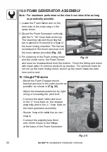
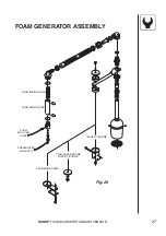
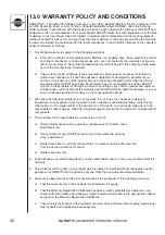
10.0 FOAM GENERATOR ASSEMBLY
Note - For maximum performance the clear hose should be as long
as practically possible.
1. Locate the Foam Generator on the
front side of the outer wing of the
spray boom.
2. Mount the Foam Generator vertically,
with the
3
/
4
” 90° hose barb at the top.
The retaining clip and mounting fl at
bar is placed to fi t around the base of
the foam mixing chamber. The fl at bar
is clamped to the boom structure with
the hose clamps provided (
Fig. 24
).
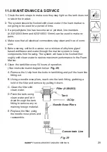
3. For cleaning of the Foam mixing mesh
and the check valve, the Foam Gener-
ator must be dis as sem bled from the bottom. Flush the fi tting and mesh
with clean water to remove any built up residue. For optimum foam do
not roll up the foam mixing mesh, bunch up the mesh inside the tube
from end to end.
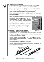
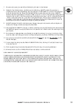
10.1 Eagle™ Booms
- Mount the Foam Dropper mount
bracket as close to the outer nozzle as
possible as shown in (
Fig. 25
).
- Adjust the breakaway tension by tight-
ening or loosening the pivot bolt.
- Connect the clear reinforced hose
to the
3
/
4
” hose barb on the dropper
assembly and to the
3
/
4
” hose barb on
the foam generator assembly.
- Secure hose with cable ties as nec-
essary.
- Connect the polyethylene 8mm
and 10mm hoses to the fi ttings
at the base of the Foam Generator.
Fig. 25
Fig. 24


