background image

36

HARDI

®

 EAGLE 3PT BOOM OPERATORS MANUAL

6.5 Adjusting Front Fold Cable

The performance of the EAGLE 3 Point Boom, while spraying, depends
greatly on the front fold cable adjustment. A correctly adjusted cable will
also control the movement of the outer wing section.

WARNING:

THE REAR CABLE CAN SNAP AND INJURE YOU OR
SOMEONE ELSE IF TENSIONED WHEN THE BOOM IS
UNFOLDED. ALWAYS ADJUST THE FRONT CABLE
FIRST WITH THE BOOM UNFOLDED AND REAR CABLE
LAST WITH THE BOOM FOLDED IN TRANSPORT POSI-
TION.

1. Unfold boom into operating position.
2. Shut the tractor off.
3. Check the security of turnbuckle anchors to the hinge.
3. Slide a straight edge down the underside of the intermediate boom

section until it just contacts the front cable.

4. Suspend a 10lb (4.5kg) weight from the straight edge-to-cable contact

point and check deflection by measuring the distance from the
straightedge to the cable. Cable should deflect .50-.75 in. (13-20mm).

5. Loosen jam nuts (

A

)(Fig. 15) on the turnbuckle assembly and adjust

turnbuckle (

B

)(Fig. 15) for proper cable deflection.

6. Tighten jam nuts (

A

)(Fig. 15) and remove weight.

IMPORTANT:

 Check boom alignment again. If front cable was tight-

ened, the wing assembly will move forward; or if loosened, wing will
move rearward. Adjust fold cylinder (if necessary) as described in
Aligning Wing Assemblies, (Section 6.3).

Fig. 15

Summary of Contents for EAGLE 3PT Boom

Page 1: ...EAGLE 3PT Boom 10521903 10 91 Operator s Manual ...

Page 2: ......

Page 3: ...tor s Manual 105219 10 99 HARDI reserves the right to make changes in design material or specification without notice thereof HARDI and other product names are registered trademarks of HARDI Inc in the U S and in other countires ...

Page 4: ...2 Performing Final Inspection 23 5 0 OPERATING THE EAGLE 3PT BOOM 24 5 1 Folding Unfolding the 3 pt Boom HY HT booms only 24 5 2 Operating the Wing Tilt If applicable 25 5 3 Folding Unfolding Booms HZ Hydraulics 25 5 4 Folding One Side Only HZ Hydraulics only 26 5 5 Nozzle Selection 26 5 6 Calibration 29 6 0 ADJUSTMENTS 33 6 1 Adjustments Maintenance Intervals 33 6 2 Checking Adjusting Sprocket Ti...

Page 5: ... 52 8 8 Checking Ball Seat in EC Controls 53 8 9 Checking the Valve Cone in Distribution Valves 53 8 10Changing the Valves Diaphrams in a 361 462 Pump 54 8 11Centrifugal Sprayer Plumbing Diagram 55 8 12Operation of the ESC Controls 56 8 13Adjustment of the ESC Controls 57 8 14Agitation Adjustment agitation nozzles only 58 8 15Control Box for Electric Control Units 59 9 0 TRANSPORTATION AND STORAGE...

Page 6: ...4 HARDI EAGLE 3PT BOOM OPERATORS MANUAL ...

Page 7: ...fore using your equipment You will find many helpful hints as well as important safety and operation information Some of the features on your EAGLE 3PT boom were suggested by growers There is no substitute for on farm experience and we invite your comments and suggestions Please address your correspondence to the Service Manager at one of these branches Sincerely Tom L Kinzenbaw President HARDI HA...

Page 8: ...6 HARDI EAGLE 3PT BOOM OPERATORS MANUAL HARDI EAGLE 3PT Boom shown mounted on tractor Fig 1 HARDI EAGLE 3PT Boom shown in storage position Fig 2 ...

Page 9: ...s simultaneous boom wing folding The HT features simultaneous wing fold and individual wing tilt through three tractor double acting outlets The HZ features electric hydraulic wing fold same as HY plus individual wing tilt This will require two tractor double acting outlets and a 12v power supply The hydraulic hoses that attach to the tractor are fitted with 1 2 NPT quick couplers The EAGLE 3 poin...

Page 10: ...D OPERATORS MANUAL BEFORE USING EQUIPMENT DO NOT REMOVE ANY SAFETY DEVICES OR SHIELDS NEVER SERVICE CLEAN OR REPAIR A MACHINE WHILE IT IS OPERATING WARNING ALWAYS WATCH FOR THIS SYMBOL TO POINT OUT IMPORTANT SAFETY PRECAUTIONS IT MEANS ATTENTION BECOME ALERT YOUR SAFETY IS INVOLVED ...

Page 11: ...per instructions Keep your EAGLE 3PT boom in proper working condition Unauthorized modifications or use may impair the function and or safety and affect the spray boom s life If you do not understand any part of this manual and need assistance please contact your authorized HARDI dealer 2 2 Operating The EAGLE 3PT Boom Safely 1 Read the complete manual carefully and become familiar with the operat...

Page 12: ...some part of the machine 10 Slow down when turning especially with boom extended 11 Always keep children away from your sprayer and or tractor unit 12 Before transporting the sprayer ensure that the boom is fully folded and fully locked into transport rests and stops Ensure all locking devices are fully engaged whether hydraulic or mechanical 13 Slow moving tractors and spray equipment can create ...

Page 13: ...yer where chemicals will not drift or run off to contaminate people animals vegetation water supply etc Locate this area where there is virtually no chance of children being in contact with this residue 5 Decontaminate equipment used in mixing transferring and applying chemicals after use Follow the instructions on the chemical label for the correct procedure required Wash spray residue from outsi...

Page 14: ...__________________________________________ 2 ___________________________________________________ 3 ___________________________________________________ 4 ___________________________________________________ 5 ___________________________________________________ 6 ___________________________________________________ 7 ___________________________________________________ 8 _______________________________...

Page 15: ... BOOM Refers to the boom in transport position 4 UNFOLDED BOOM Refers to the boom in the spraying position 5 WING Refers to the folding portion of the boom 6 LIFT FRAME Mounts to the upper and lower parallelogram arms 7 CENTER SECTION Refers to the portion of the boom that the wings attach to The wings move up and down with the center 8 LINK ARMS Attaches the Center Section to the Lift Frame 9 INT...

Page 16: ...y 2 Wing assembly RH 3 Wing assembly LH 4 3 point hitch frame 5 Boom mount kit 4 1 Attaching Center Frame to 3 point Hitch Frame WARNING CENTER FRAME WILL NOT STAND ON ITS OWN EVEN WITH 3PT HITCH FRAME ATTACHED IT IS ADVISABLE TO ATTACH THE 3PT HITCH FRAME TO TRACTOR HITCH BEFORE STARTING TO ASSEMBLE THE SPRAYER Fig 4 Attach center frame to hitch frame with 4 2 x6 x3 8 clamping plates A and 8 5 8 ...

Page 17: ...all 0 ring washers and restrictor fittings in both ports on hydraulic cylinders The restrictor with the small hole is fitted to the fixed base end of the hydraulic cylinder Fig 7 2 Position boom hinge on center frame with folded boom sections to the front 3 Attach tie rod tilt cylinder to hinge pin and cotter pins 4 Line up lower hinge pin holes and insert pin Insert threaded pin from the front th...

Page 18: ...OR LEAKS WITH A PIECE OF CARDBOARD NOT YOUR HANDS IMPROPER HOOK UP CAN CAUSE DANGEROUS BOOM MOVEMENTS AND OR DAMAGE TO THE SPRAYER HYDRAULICS DO NOT ALLOW ANYONE NEAR A HYDRAULIC BOOM IN OPERATION ALWAYS SHUT TRACTOR OFF WHEN CONNECTING SERVICING OR ADJUSTING BOOM IMPORTANT Due to the wide variations in tractor hydraulic systems and capacities care should be exercised when initially operating the ...

Page 19: ... to fold cylinders Section 9 0 2 If hydraulic tilt cylinders are fitted to spray boom air should be bled from these lines before spraying 3 Disconnect tilt cylinder rod eyes from wing section IMPORTANT WING SECTION MUST BE SUPPORTED BEFORE REMOVAL OF HYDRAULIC CYLINDER ROD EYES 4 Ensure cylinder is free for retraction and extension 5 Start tractor engine and cycle fold cylinders by actuating doubl...

Page 20: ...gether to keep the center frame square to the stationary frame while folding boom in for transport or when spraying with one side raised and folded HT and HZ only 1 Fold boom into transport position 2 Shut the tractor off 3 Check that the tilt cylinders are COMPLETELY EXTENDED Adjust if necessary HT and HZ only 4 Loosen jam nuts C Fig 9 5 Check that the cables are routed over the center section no...

Page 21: ...ARE FOLDED 6 Retain all hoses with tie straps IMPORTANT ALTERNATE FROM SIDE TO SIDE WHILE MAKING ADJUSTMENTS ADJUST ONE CABLE A SMALL AMOUNT AND THEN THE OTHER TO EQUALIZE CABLE TENSION AND MAINTAIN A LEVEL CENTER FRAME DO NOT OVERTIGHTEN THE CABLE ADJUST TENSION UNTIL BELLEVILLE WASHERS JUST START TO COMPRESS NOT BEYOND 6 Adjust jam nuts as above 7 Properly adjusted cables will be very tight and ...

Page 22: ...BE SURE OF FITTING LOCATIONS PRIOR TO ATTACHING HOSES PLACTIC FITTINGS USE VERY AGGRESSIVE HOSE BARB WHICH MAKES HOSE REMOVAL DIFFICULT 5 Attach hoses to T piece using clamps 6 Install adapter fittings in outer hose ends using clamps 7 Lubricate adapter fitting radial seals using vegetable based oils 8 Attach hose to center sections inner spray tube ends with T inlet directed to rear of sprayer 9 ...

Page 23: ...NSURE ALL CONNECTIONS ARE TIGHT BEFORE APPLYING PRESSURE SEARCH FOR LEAKS WITH A PIECE OF CARD BOARD NOT YOUR HANDS IMPROPER HOOK UP CAN CAUSE DANGEROUS BOOM MOV MENTS AND OR DAMAGE TO THE SPRAYER HYDRAULICS DO NOT ALLOW ANYONE NEAR A HYDRAULIC BOOM IN OPERATION ALWAYS SHUT TRACTOR OFF WHEN CONNECTING SERVIC ING OR ADJUSTING BOOM IMPORTANT Due to the wide variations in tractor hydraulic systems an...

Page 24: ... be used 2 Connect plug F Fig 10 to the tractor s 12V power system Try to hook up the handle as close as possible to the battery or the starter for a better power supply HARDI recommends using electric distribution box 817925 to insure a good power supply to various 12V attachments Note Check with your dealer or tractor operators manual for the best location to hook up the 12V system Note polarity...

Page 25: ... plate to the tractor 3 Mount the DH hydraulic switch box in a suitable location in the tractor cab 4 Connect the bayonet plug from the switch box to a 12V power supply HARDI recommends using electronic distribution box 817925 to ensure a good power supply to various 12V attachments Note polarity BROWN WIRE POSITIVE BLUE WIRE NEGATIVE 5 Connect the female 7 pin plug from the switch box to the 7 pi...

Page 26: ...E BOOM ENSURE THAT THE SAFETY CHAINS ARE FITTED BETWEEN THE CENTER FRAME AND WING SECTIONS BEFORE TRANSPORTING AND STORING THE EAGLE 3PT BOOM 5 1 Folding Unfolding the 3 point Boom HY and HT booms only 1 Disconnect safety chains from wings 2 Activate the tractors double acting hydraulic lever to unfold the boom Both wings will unfold simultaneously 3 Set the desired spray height by raising or lowe...

Page 27: ...aulic Joystick Controls 1 Raise the boom to clear any obstructions 2 Depress switches A B and move hydraulic handle forward or rearward to activate oil flow Switch positions of the hoses in the double acting remote outlet if you do not like the direction required to activate the boom 3 One side folding will be achieved by following the above procedure except that only one of the switches is depres...

Page 28: ...f nozzle and calibration of the sprayer are critical to achieve accurate and cost effective use of farm crop protection products Your HARDI sprayer has been supplied with 110 flat spray Green Color Tips that will apply approximately 20 U S GPA at 30 PSI and 5 MPH The 110 flat spray nozzle was chosen rather than the 80 degree nozzle for two reasons 1 It may be used at a lower minimum height which r...

Page 29: ...ngles For herbi cides insecticides and fertilizer applications 50 80 and 100 meshscreensarenormallyused 4665 65 degree 2080 80 degree 4110 110 degree Part 330013 O ring HOLLOW CONE NOZZLES for high pressure and high volume insecticide application in row crops 1553nozzlesareALWAYS used with swirl plates shown be low EXCEPT when used as solid stream nozzles 50 80 or 100 mesh screens are normally use...

Page 30: ...c tion with cone nozzle to create desired spray pattern These swirlsworkwith1553seriescone nozzles Grey blue or black swirls are used to create hollow coneeffect Whiteswirlsareused to create full cone effect Grey Blue Black White LARGEDROPLETFLATSPRAY TIP IN 150 DEGREE SPRAY ANGLE Always used in conjunc tion with 1553 14 16 18 or 20 cone nozzle 50 80 or 100 mesh screens are normally used with thes...

Page 31: ...libration Following are some tips to remember when using the calibration kit method Whendeterminingthelengthoftimerequiredtodrivetherecommended distance drive in actual field conditions with a half full tank Repeat the test several times each time avoiding the tracks from the previous test Take the average of the times recorded Calibration of the sprayer should be completed at the beginning of the...

Page 32: ...spacing Row width or nozzle spacing in Distance ft 40 102 38 107 36 113 34 120 32 127 30 136 28 146 26 157 24 170 22 185 20 204 18 227 16 255 14 291 2 Measure the amount of time it takes you to travel the test strip when throttle is set at spraying speed 3 In a container with oz measurements catch the spray from on nozzle for that amount of time For drop or band nozzles catch the spray from all no...

Page 33: ... either the nozzle wheel if nozzle spacing is 20 inches or this formula Formula Formula GPM GPA x MPH x W in GPM 10 x 7 x 20 24 GPM 5940 5940 Note W Nozzle spacing in inches for broadcast application Row spacing in inches divided by number of nozzles per row for drop nozzle application Sprayed band width or swath width in inches for band application divided by number of nozzles per band Note that ...

Page 34: ...00 lbs gal 96 98 8 34 lbs gal water 1 00 1 00 9 00 lbs gal 1 08 1 04 10 00 lbs gal 1 20 1 10 10 65 lbs gal 28 N 1 28 1 13 11 00 lbs gal 1 32 1 15 12 00 lbs gal 1 44 1 20 14 00 lbs gal 1 68 1 30 Example 20 GPA of 28 N Then GPA solution x conversion factor GPA water 20 GPA 28 N x 1 13 22 6 GPA water Calibrate for 22 6 GPA of water For conversion to Imperial gallons per acre multiply U S GPA by 833 F...

Page 35: ...n the factory The boom however will require additional adjustments shortly after being taken into service 10 hours and thereafter on a minimum annual basis to perform at its maximum levels To further insure the booms proper performance the Eagle 3 point boom also has to be maintained on a regular basis PLEASE FOLLOW THE SUGGESTED MAINTENANCE INTERVALS Perform the adjustment procedures in the same ...

Page 36: ...m check to ensure that the 7th pin connection inthetimingchain onthe48 and66 boom A Fig 12 isalignedwith the center line between the sprocket cap screws B Fig 12 2 To adjust timing loosen the turnbuckles on the front and rear cables until slack 3 Line up the chain and sprocket as indicated in step 1 4 Adjust front and rear cable tension Section 6 10 Right Wing Sprocket Fig 12 ...

Page 37: ...the intermediate section needs to be adjusted to the front or rear to come into alignment with center frame Note Because of adjustments made later it is better to start with the wing assemblies angled slightly to the rear 3 Relieve pressure from cylinder by folding the boom in a few inches 4 Disconnect cylinder rod eye B Fig 13 from the intermediate boom section Note Some cylinder rods have a mach...

Page 38: ...ck the security of turnbuckle anchors to the hinge 3 Slide a straight edge down the underside of the intermediate boom section until it just contacts the front cable 4 Suspend a 10lb 4 5kg weight from the straight edge to cable contact point and check deflection by measuring the distance from the straightedge to the cable Cable should deflect 50 75 in 13 20mm 5 Loosen jam nuts A Fig 15 on the turn...

Page 39: ...ut Note Spring pressure from tensioned breakaway clutch only assists in returning outer boom section to alignment 3 Check that the lower nut D Fig 16 is fully tightened 4 The breakaway wing section should pivot around the axle shaft E Fig 16 Ensure that section F Fig 16 is free to move 5 Loosen jam nut B Fig 16 6 Tighten nut C Fig 16 to stiffen clutch action Clutch is properly tensioned when break...

Page 40: ... HY Booms 1 Loosen jam nut A Fig 17 2 Adjust nut B Fig 17 in or out until wing is level to ground 3 Secure jam nut A Fig 17 Same procedure applies to both sides Fig 17 Fig 18 C HZ and HT Booms 1 Ensure cylinder is fully extended 2 Loosen jam nut A Fig 18 3 Apply an adjustable wrench to the machined surface at B Fig 18 4 Turn the cylinder rod until boom is level to the ground 5 Secure jam nut A Fig...

Page 41: ...housing 6 Secure the jam nut B Fig 20 7 Pressurize cylinder to see if the boom is properly adjusted If not repeat the above procedure until it is correctly adjusted 6 8 Adjusting The Center Section This adjustment will affect the suspension trapeze function and must therefore be done properly to optimize the EAGLE 3 Point Boom perfor mance IMPORTANT Lubricate pivot linkage and grease skid plates p...

Page 42: ...ion Fold the boom to transport position with the tilt cylinders fully extended Make sure the fold cylinders are pressurized and that the boom is folded all the way in 2 Shut the tractor off 3 Ensure the boom transport stop arms are in contact with the outer wing Adjust if necessary 4 Loosen the jam nuts on the turnbuckle Adjust tighten the turnbuckle so that the outer wing section contacts the boo...

Page 43: ...es the center frame as well as the boom hinges and breakaway clutches 7 2 Greasing the Center Frame Every 8 hours daily new grease should be applied to the wear surfaces on the center frame Fig 21 Every 50 hours the grease on the center frame should be completely cleaned off with a degreasing solvent and new grease applied Follow the above steps when doing this Fig 21 7 3 Greasing The Suspension P...

Page 44: ...WARNING NEVER PLACE FINGERS INTO OPEN BREAKAWAY CLUTCH OR YOU MAY BE INJURED SHOULD CLUTCH SNAP CLOSED 1 Unfold the boom into operating spraying position 2 Standinginfrontoftheouterwing snapthebreakawayopenbyquickly pushing the boom away from you 3 With the two clutches opened up stick the nozzle of a grease gun into the clutch and apply a generous amount of grease This should be done every 8 hour...

Page 45: ... 7 8 Nozzle Tubes And Fittings Poor seals are usually caused by Missing O rings or gaskets Damaged or incorrectly seated O rings Dry or deformed O rings or gaskets Foreign materials Therefore in case of leaks DO NOT overtighten any fittings Fig 24 Disassemble check the condition and position of the O ring or gasket clean lubricate and then reassemble For radial seals O rings Fig 24 only hand tight...

Page 46: ...triplet assembly Clean the bottom part as well as the top part thoroughly Coat the O ring with a light film of vegetable oil if the sprayer is to be stored for a long period of time If the triplets are not cleaned regularly they will not rotate readily and possible damage to them may occur Fig 25 WARNING NEVER SERVICE YOUR CONTAMINATED NOZZLES WITHOUT WEARING CHEMICAL RESISTANT GLOVES AND SAFETY G...

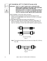
Page 47: ...TS CAN BE ROTATED BY HAND TO FACILITATE SPLINE ALIGNMENT WHEN ENGINE IS STOPPED When attaching the shaft make sure that the snap lock is FULLY ENGAGED push and pull shaft until it locks WARNING ROTATING TRANSMISSION SHAFTS WITHOUT PROTECTION GUARDS ARE FATAL Always keep protection guards and chains intact and make sure that it covers all rotating parts including CV joints at each end of the shaft ...

Page 48: ...ADJUSTMENTS ARE COMPLETED Initial installation of the shaft is done as follows 1 Attach the 3 point sprayer to tractor and set the sprayer in the position with the shortest distance between the tractor and sprayer pump P T O shafts 2 Stop the tractor engine and remove the ignition key 3 If the P T O shaft must be shortened the shaft is pulled apart Fit the two shaft parts at tractor and sprayer pu...

Page 49: ...wards to remove burrs Fig 29 5 Grease the profiles and assemble male and female parts again 6 Fit the shaft to tractor and sprayer pump Note Female part towards tractor Fit the chains to prevent the protection guards from rotating with the shaft Fig 30 7 To ensure long life of the P T O shaft try to avoid working angles greater than 15 Fig 30 ...

Page 50: ...se Should be used with a minimum of a 30 mesh filter or larger in this hose B Self cleaning filter to safety valve 1 hose the safety valve is supplied in kit and must be fitted to sprayer tank C Agitation hose 1 2 hose from adjustable agitation valve D Constant pressure return hose 1 hose from Electric Control Unit E Return line from main on off valve 1 hose from Electric Control Unit F Safety val...

Page 51: ... in neutral and adjust the P T O RPM s until the number of revolutions of the pump corresponds to the intended traveling speed Remember the number of revolutions on the P T O must be kept between 300 600 rpm 3 Open or close knob 5 Fig 32 depending on whether pressure agitation is required Remember pressure agitation takes 5 to 10 of pump output 4 On off switch A Fig 33 is ON against green dot 5 Al...

Page 52: ...iving In order to shut off the entire boom activate on off switch A Fig 33 This returns all the pump outputs to the tank through the return system The diaphragm anti drip valves ensures instantaneous closing of all nozzles In order to shut off one or more sections of the boom switch one or more unneeded boom distribution valves B Fig 33 to off position The constant pressure device ensures that the...

Page 53: ...products tend to foam easily To reduce foaming in some instances anti foaming agents may be added to the tank Refer to chemical label When running low liquid levels in the tank agitation may be reduced to facilitate pump priming and avoid pressure fluctuations Make sure that you have adjusted the agitation properly before sprayer calibration Turning the Agitation Valve A Fig 34 clockwise will redu...

Page 54: ...screens may be installed for various types of products A good practice is having the necessary new O rings on hand at the time of changing screens or when performing routine maintenance O ring part numbers are 242020 241953 242047 Note It is advisable to have the sprayer tank empty before carrying out any maintenance on the self cleaning filter To clean or replace filter loosen nut 6 Fig 35 to rem...

Page 55: ...ssary Fig 36 8 9 Checking the Valve Cone in Distribution Valves Periodically check the distribution valves for proper sealing 1 Flush the sprayer with clean water and open master on off and all distribution valves Shut sprayer off 2 Remove clip A Fig 37 and remove hose B Fig 37 for the constant pressure device When the housing is drained make sureeverythingisclearfrompart B Fig 37 3 Start the spra...

Page 56: ...s 2 Fig 38 note the orientation of the valves so that they are replaced correctly IMPORTANT The two valves with vented flaps 2A and 2B Fig 38 must be placed in the valve openings as shown 2 It is recommended to use new O rings 3 Fig 38 330024 when changing or checking the valves 3 Remove the diaphragm bolt 4 Fig 38 after having dismantled the valve cover as indicated above The diaphragm 5 Fig 38 m...

Page 57: ... connected to the spray tanks fitted to the tractor Refer to Fig 39 A Suction hose to pump 1 1 2 hose Should be used with a minimum of a 30 mesh filter or larger in this hose B Agitation hose 1 2 hose from adjustable agitation valve C Constant pressure return hose 1 hose from Electric Control Unit If the tanks to be used are polyethylene HARDI can supply bulkhead fittings with quick disconnect fea...

Page 58: ...Adjustment screw for constant boom pressure 2 Pressure control valve 3 Distribution valves 4 System pressure gauge 5 System pressure filter ESC Control Box A Master operating switch for on off valves B Operating switches for ditribution valves C Pressure regulating switch lower raise Fig 40 Fig 41 ...

Page 59: ...on at a time as follows Start with the valve turned closed before adjusting 7 Shut off the first boom distribution valve switch B Fig 41 8 Turn the adjusting screw 1 Fig 41 until the control unit pressure gauge 7 Fig 40 again shows the same pressure as set in step 6 above Turn the screw clockwise for higher pressure counterclock wise for lower pressure 9 Turn the first boom distribution valve swit...

Page 60: ... clockwise will increase the agitation flow In order to shut off one or more sections of the boom switch one or more unneeded boom distribution valves B Fig 41 to off position The constant pressure device ensures that the pressure does not increase in the sections which are still operating In case of electrical failure it is still possible to manually overide all functions of the operating unit To...

Page 61: ...e back cover which need to be drilled out for mounting on a flat surface There should be a minimum of a 8 amp fuse protecting this circuit Power requirement is 12 volt DC Note polarity Brown positive Blue negative Use the optional HARDI Electric 12 volt outlet box No 817925 if more than one power outlet is required 12 volt junction box for 12 volt hook up EC ECS controls HARDI PILOT boom hydraulic...

Page 62: ...ELF OR SOMEONE ELSE KNOW THE TRANSPORT HEIGHT OF YOUR MACHINE Keep all persons away from machine when folding boom It is imperative that safety chains are attached between center section and boom wings before storing or transporting sprayer Transport 3 Point Eagle boom only with booms folded Maximum transport speed is 15 mph 24 km h Have warning lights flashing when transporting or towing sprayer ...

Page 63: ...e sprayer according to the instructions given with the chemical used Store sprayer in a safe dry location away from children and animals Protect from direct sunlight TO PLACE SPRAYER IN STORAGE a Lower parking stands into position refer to Fig 45 b Lower the tractor 3 point hitch lift arms to park the boom on its stands c Disconnect sprayer hydraulics from tractor hydraulics d Disconnect PTO shaft...

Page 64: ... plug PTO Transmission Shaft If applicable Check that the transmission shaft is in good working condition e g that the shield and protective tubes are in place and in good condition Anti freeze Precaution If the EAGLE 3 point boom is not stored in a frost free place you should take the following precautions 1 Drain as much water as possible from spray boom hoses and nozzle tubes 2 Pour in a mixtur...

Page 65: ...cylinder C Bleed air from hydraulic sys tem A Check for proper 12V power supply A Checkfordefectiveswitch s B Check continuity of cables C Check for operation of appli cable solenoid coil not acti vating or plunger stuck D Check for short circuit in wir ing juction box at rear of sprayer E Dirt in the restrictor port of the cylinder A Check for correct solenoid electric hydraulic hook up B Check f...

Page 66: ...tric continuity through multi pin plugs Solution A Adjust the fold cylinder Section 7 3 A Check adjustment of center cables Section 7 12 A Adjust and grease complete boom cables and stops Section 7 0 A Check for hydraulic leak through solenoid block B Check for a solenoid that is stuck open A Boom must be completely unfolded then fold the de sired wing in B Check for hydraulic leak through solenoi...

Page 67: ...OLD RIGHT FOLD L 2900 L 2750 L 2750 9 0 9 6 9 0 L 2900 9 6 L 170 7 7 L 170 TO TRACTOR L 4500 14 9 LEFT FOLD RIGHT FOLD L 2750 9 0 L 2900 9 6 TO TRACTOR L 4500 14 9 L 2750 9 0 L 2900 9 6 10 3 Hydraulic Schematics A HY Schematics B HY OPTION Schematic ...

Page 68: ... L 4500 14 9 LEFT TILT L 4200 L 4500 14 9 13 9 RIGHT TILT L 4200 13 9 L 4500 14 9 TO TRACTOR C HT Schematic D HZ Schematic LEFT FOLD RIGHT FOLD LEFT TILT RIGHT TILT TO TRACTOR L 3000 9 10 L 3000 9 10 L 3100 10 2 L 3100 10 2 L 2450 8 0 L 2450 8 0 L 2300 7 6 L 2300 7 6 L 5320 17 5 A B P T DH Optional TO SOLENOID VALVE BLOCK TO TRACTOR ...

Page 69: ...gweak or broke E No restrictor plate in self cleaning filter F Crackedinternalhousingorbad seal on HARDI matic valve G Motor shaft coupling loose or fork pin missing H Bad seat on spool valve for boom section control I PTO speed not fast enough J Flush valve not in correct position Units equipped with Flush Rinse system only K Bad suction valve or suction side air leak L P T O not engaged M Rinse ...

Page 70: ...a disturbance around suction tube B Suction filter plugging C Pump valve broke or seat missing D PTO shaft slipping on pump crankshaft E Crackedinternalhousingorbad seal on HARDI matic valve F Bad seat on spool valve for boom section control G Bad suction valve or suction side air leak 5 Liquid leaking from pump A Damaged pump diaphragm 6 Electric control not functioning A Motorbadormicro switchpl...

Page 71: ... not the right size E Bad suction valve or suction side air leak F Rinse valve not in correct position Unit equipped with Flush Rinse system only 10 Can t get tank empty A Output from by pass lines causing a disturbance around suction tube B Crack or pin hole in suction tube C Tank is not level change angle of tongue 11 Boom nozzle leaking A Seat on master shut off valve worn or cracked B Bad seat...

Page 72: ... make foam B Not enough foam concentrate C Solenoid valve plugged D Solenoid not working 3 Will not make enough foam A Line leak or line pinched B Solenoid valve plugged C Weak foam concentrate mixture D Water too hard add water softener 4 Foam drops will not last A Not enough foam concentrate B Frequency valve not opened enough C Weak foam concentrate D Water too hard Add water softener 5 Keeps b...

Page 73: ...iller pressure selection not in correct posi tion if so equipped 10 7 Chemical Filler 1 Filler tank will not empty A Pressure selection valve not in correct position B Sprayer pump not running 2 Filler tank empties too slow A Bottom tank discharge valve not open all the way B Restrictor cone from pump supply not the correct size Black 361 pump White 462 pump 3 Filler tank backfills when bottom A R...

Page 74: ...m shown A handy source of fresh water on the sprayer to clean up plugged nozzles andforrinsingglovesand handsafterperformingserviceormaintenance 11 2 Pump Control System Fig 47 Fig 48 To provide a self contained 3 point hitch mounted spraying system two PTO driven pumps control systems are available to mount to the EAGLE 3 point Boom ...

Page 75: ...ver lapping during spray application of solution both which can be costly HARDI Foam Marker features a trailer mounted compressor poly tank extruded foamer hoses and in cab electrical controls providing right or left drop selection and the rate quality of foam droplets Foam Marker Tank Compressor Foam Marker Drop Assembly ...

Page 76: ...25ft of hose for spraying fence row or spot spraying a small area can be installed onto your sprayer A handy hose wrap and handgun holder can be conveniently located on the sprayer to transport the handgun 1000 RPM Gearbox Drive provides a means to use larger tractors having only 1000 RPM PTO system Available for the model 361 and 462 pumps only The gearbox has an oil filled case to provide long l...

Page 77: ...ances within or without the warranty period will HARDI be liable for damages of loss of use or damages resulting from delay or any consequential damage 2 We cannot be held responsible for loss of livestock loss of crops loss because of delays in harvesting or any expense or loss incurred for labor supplies substitute machinery rental for any other reason or for injuries either to the owner or to a...

Page 78: ... at 80 during the fifth year This five year extended warranty is subject in each instance to the tank being inspected and approved for replacement or repair by HARDI personnel before HARDI will accept any liability hereunder 10 HARDI reserves the right to incorporate any change in design in its products without obligation to make such changes on units previously manufactured 11 The judgement of HA...

Page 79: ......

Page 80: ...06 Fax 559 271 3107 HARDI GREAT LAKES 290 Sovereign Rd London Ontario N6M 1B3 Phone 519 659 2771 Fax 519 659 2821 For Product Service or Warranty Information Please contact your local HARDI dealer To contact HARDI directly Please use the HARDI Customer Service number 1 866 770 7063 Or send your email to CUSTSERV hardi us com HARDI INC Visit us online at www hardi us com ...

Reviews: