3 - Description
3.5
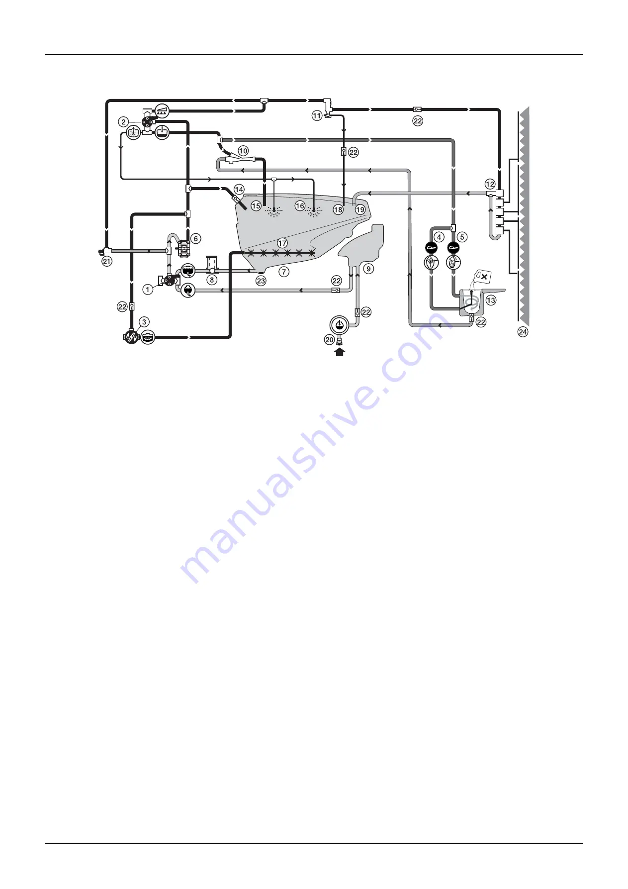
1. Suction SmartValve
2. Pressure SmartValve
3. Agitation valve
4. Chemical container cleaning grip
5. ChemFiller Vortex nozzle
6. Pump
7. Main tank
8. EasyClean filter
9. Rinsing tank
10. Ejector
11. CycloneFilter
12. Section valves
13. ChemFiller
14. SafetyValve
15. Ejector filling inlet
16. Internal tank cleaning nozzles
17. Agitation
18. Return line for boost function
19. Return from distribution valves
20. Rinsing tank coupler
21. PressureControl valve
22. One-way valve
23. Drain valve
24. Sprayer boom
Diagram - LookAhead Liquid system
Summary of Contents for COMMANDER TWIN FORCE 3200
Page 8: ...Table of contents TOC 6 ...
Page 10: ...1 CE Declaration 1 2 ...
Page 14: ...2 Safety notes 2 4 ...
Page 66: ...6 Maintenance 6 2 Boom lubrication oiling plan 32 36 m ...
Page 67: ...6 Maintenance 6 3 Trailer lubrication oiling plan ...
Page 107: ...8 Technical specifications 8 11 Charts Boom hydraulic Y Boom hydraulic Z ...
Page 108: ...8 Technical specifications 8 12 Sprayer hydraulic Fan transmission ...
Page 109: ...8 Technical specifications 8 13 Electrical specifications for boom and work light ...
Page 110: ...8 Technical specifications 8 14 ...


