


29
HARDI
®
COMMANDER OPERATOR’S MANUAL
IMPORTANT!
The yellow MANIFOLD valve should
normally be open, but must be closed in the following
cases:
1. If rinsing with water from the flush tank and a quan-
tity of spray liquid still remains in the main tank
(otherwise the spray liquid will be diluted).
2. If opening the self-cleaning filter and a quantity of
spray liquid still remains in the main tank (otherwise
there is a risk that spray liquid will flow out).
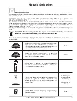
Choice of correct restrictor for S.C.F.
It is important to have a large flow through the self
cleaning filter. This is achieved by choosing the
restrictor size in relation to the liquid consumption of
the spray boom.
The hose (
A
) is unscrewed
from the self-cleaning filter.
Be careful not to lose the
seal ball or spring when
the restrictor is put in the
hose and the hose is
refitted. If the required
working pressure can not
be obtained, the restrictor
is too large. 4 restrictors
are supplied. Use the
green
one (largest orifice)
first. Then choose the next
smaller restrictor, starting
with
black
, then
white
and finally a
red
one.
Adjustment of Air Pressure in Pressure
Damper (1302 Pump Only)
The air pressure in the damper on
the 1302 pump is factory preset at
30 psi (2 bar). This is suitable for
nozzle spray pressures between
45 psi (3 bar) and 225 psi (15
bar). If different nozzle pressures
are required, set pressure damper
at pressures indicated.
Remote 4” pressure gauge
The remote pressure gauge is integrated into the front
locker. This gauge measures the working pressure in
the boom tubes as close to the nozzles as possible.
This pressure reading will always be slightly lower than
the reading at the operating unit pressure gauge.
The outputs stated in the nozzle charts are always
based on the pressures measured at the nozzle.
Note:
Always adjust pressure when calibrating and spray-
ing according to readings at the Remote pressure gauge.
Self cleaning filters
This filter automatically flushes out particles and
chemical deposits, reducing routine maintenance,
nozzle plugging and operator exposure. No adjust-
ments are required, but different mesh screens may be
installed for various types of products. The mesh size
of the filter in use should always be smaller than the
flow average of the nozzles used.
Operating diagram
1. From pump
2. Double filter screen
3. Guide cone
4. To operating unit
5. Replaceable restrictor
6. Return to tank
7. Screw-joint
The self-cleaning filter is operated via
the yellow MANIFOLD valve.
Operation
PSI (BAR)
20-45 (1-3)
45-225 (3-15)
PSI (BAR)
0-15 (0-1)
15-45 (1-3)
Open
Closed


