background image

Page 2

For technical questions, please call 1-888-866-5797.

Item 58473

WARNING SYMBOLS AND DEFINITIONS

This is the safety alert symbol.  It is used to alert you to 

potential personal injury hazards.  Obey all safety messages 

that follow this symbol to avoid possible injury or death.

Indicates a hazardous situation which, if not avoided,  

will result in death or serious injury.

Indicates a hazardous situation which, if not avoided,  

could result in death or serious injury.

Indicates a hazardous situation which, if not avoided,  

could result in minor or moderate injury.

Addresses practices not related to personal injury.

Important Safety Information

Read all safety warnings and instructions.  

Failure to follow the warnings and instructions may result in serious injury. 


Save all warnings and instructions for future reference.
DANGER! TO PREVENT SERIOUS INJURY AND/OR DEATH, ATTACH A SAFETY 

CHAIN AND PROPERLY SECURE HITCH BEFORE LOADING OR TOWING. 
WARNING! TO PREVENT SERIOUS INJURY AND/OR DEATH, DO NOT EXCEED 

MAXIMUM PAYLOAD CAPACITY OF 1,200 LB OR 5 MPH MAXIMUM SPEED. 

The warnings, precautions, and instructions discussed in this instruction manual 

cannot cover all possible conditions and situations that may occur.  It must be 

understood by the operator that common sense and caution are factors which 

cannot be built into this product, but must be supplied by the operator.

Assembly Precautions

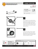
1.  Assemble only according to these 

instructions.  Improper assembly 

can create hazards.

2.  Wear ANSI-approved safety goggles and 

heavy-duty work gloves during assembly.

3.  Keep assembly area clean and well lit.

4.  Keep bystanders out of 

area during assembly.

5.  Do not assemble when tired or when 

under influence of drugs or medication.

6.  Weight capacity and other product 

capabilities apply to properly and 

completely assembled product only.

Summary of Contents for 58473

Page 1: ...n unpacking make sure that the product is intact and undamaged If any parts are missing or broken please call 1 888 866 5797 as soon as possible Copyright 2021 by Harbor Freight Tools All rights reserved No portion of this manual or any artwork contained herein may be reproduced in any shape or form without the express written consent of Harbor Freight Tools Diagrams within this manual may not be ...

Page 2: ...eference DANGER TO PREVENT SERIOUS INJURY AND OR DEATH ATTACH A SAFETY CHAIN AND PROPERLY SECURE HITCH BEFORE LOADING OR TOWING WARNING TO PREVENT SERIOUS INJURY AND OR DEATH DO NOT EXCEED MAXIMUM PAYLOAD CAPACITY OF 1 200 LB OR 5 MPH MAXIMUM SPEED The warnings precautions and instructions discussed in this instruction manual cannot cover all possible conditions and situations that may occur It mu...

Page 3: ...se attach Clevis Pin Mount to tractor Loading Safety 1 Do not exceed the Cart s maximum payload capacity of 1 200 lb properly distributed 2 Properly and safely secure the payload in the Cart Load Cart evenly front to back and side to side 3 Make sure the towing vehicle and its hitch are both rated to safely tow the Cart and its payload The towing capacity of the hitch is typically stamped on the h...

Page 4: ...ral cracks and bends and any other condition that may affect its safe operation Do not use the Cart even if minor damage appears General Handling 1 Use the driving gear that the tractor manufacturer recommends for towing 2 Drive at low speeds This will place less strain on your tow vehicle and Cart Cart instability sway is more likely to occur as speed increases Do not exceed 5 miles per hour when...

Page 5: ...off ignition e Then remove your foot from the brake pedal Following this parking sequence is important to make sure you do not harm the transmission Maintenance Safety 1 Maintain labels and nameplates on the Cart These carry important information If unreadable or missing contact Harbor Freight Tools for a replacement 2 Replacement parts and accessories when servicing use only identical replacement...

Page 6: ...wo Washers 12 and two Lock Nuts 21 onto Bolts Tighten Lock Nuts securely Yoke 11 Bolt 23 Washer 12 Nut 21 Front Axle Support 9 4 Place Front Axle Support and Yoke assembly on one Bed stud 5 Secure with Washer 24 and Nut 17 on Tighten Nut securely Bed 1 Washer 24 Nut 17 6 Place Rear Axle Support 6 on two Bed studs 7 Secure with two Washers 12 and two Lock Nuts 21 Tighten Lock Nuts securely Rear Axl...

Page 7: ...14 Align holes and insert Clevis Pin 7 15 Install Small R Pin 8 through Clevis Pin s hole until securely fastened Handle 14 Clevis Pin 7 Small R Pin 8 16 Using assistance rotate Cart assembly onto Tires 17 With Lock Handles facing out place Back Panel 4 onto rear of Bed 18 Insert two Large R Pins 16 through Back Panel and Bed hinge tubes until securely fastened 19 Repeat with other Panels Bed 1 La...

Page 8: ...rs have the problem corrected before further use Attaching the Cart to Tractor 1 Cart should be on a level surface with tires chocked 2 The tractor should be turned off braked and backed in front of the Cart s Clevis Pin Mount 3 Remove Small R Pin from Clevis Pin 4 Remove Handle 5 Join the Cart to the tractor by lining up the Clevis Pin Mount with the hole in the connector on the tractor 6 Connect...

Page 9: ...perating mechanisms for proper operation proper adjustment and unusual sounds such as but not limited to binding noise or and bearing squeal 2 Check wheels tires for wear and proper inflation Cleaning and Maintenance 1 Repair or replacement of Cart components must be performed only by a qualified technician using only identical replacement parts with the same rating 2 Note the following regarding ...

Page 10: ...R REPAIRS TO THE ORIGINAL PRODUCT OR REPLACEMENT PARTS THERETO OR ARISING OUT OF HIS OR HER INSTALLATION OF REPLACEMENT PARTS THERETO Parts List and Diagram Parts List Part Description Qty 1 Bed 1 2 Side Panel 2 3 Front Panel 1 4 Back Panel 1 5 Tire 4 6 Rear Axle Support 1 7 Clevis Pin 1 8 Small R Pin 1 9 Front Axle Support 1 10 Tire Cotter Pin 4 11 Yoke 1 12 Washer 4 13 Coupler 1 Part Description...

Page 11: ...Page 11 For technical questions please call 1 888 866 5797 Item 58473 Diagram 25 1 2 3 4 5 6 7 8 9 10 11 13 14 15 16 17 18 19 20 21 22 23 24 12 21 21 21 ...

Page 12: ...damages so the above limitation of exclusion may not apply to you THIS WARRANTY IS EXPRESSLY IN LIEU OF ALL OTHER WARRANTIES EXPRESS OR IMPLIED INCLUDING THE WARRANTIES OF MERCHANTABILITY AND FITNESS To take advantage of this warranty the product or part must be returned to us with transportation charges prepaid Proof of purchase date and an explanation of the complaint must accompany the merchand...

Reviews: