Harbor Freight Tools 47078, Assembly & Operating Instructions
The Harbor Freight Tools 47078 is a versatile and reliable product designed to make your tasks easier. Along with the product, a comprehensive assembly and operating manual is available for free download on our website. Refer to the manual to ensure proper usage and maximize the benefits of this exceptional tool.
Share
Download


Reviews:
No comments
Related manuals for 47078
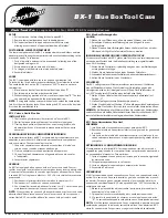
BX-1
Brand: Park Tool Pages: 2

Spectra 2K Library
Brand: Spectra Logic Pages: 93

DiamondMax Plus9 120GB AT
Brand: Maxtor Pages: 79

DUO LINK
Brand: PNY Pages: 17

K8114
Brand: kincrome Pages: 2

1034594
Brand: Lifetime Pages: 20

Hybrid Home 4,8
Brand: Hybrid Pages: 42

BARRACUDA 18FC
Brand: Seagate Pages: 32

ROCPRO 225
Brand: Rocstor Pages: 45

sasbeast
Brand: Nexsan Pages: 6

MERCURY ELITE PRO MINI
Brand: OWC Pages: 8

23151SK-PTX
Brand: ABSCO SHEDS Pages: 19

TVS-h1688X
Brand: QNAP Pages: 16

1013 TYZ
Brand: Yardmaster Pages: 28

Storage 6180 Array
Brand: Oracle Pages: 6

StorageTek SL3000
Brand: Oracle Pages: 216

Pillar Axiom 600
Brand: Oracle Pages: 229

SATA
Brand: TrekStor Pages: 48


