background image

8

Lowes.com/harborbreeze

INITIAL INSTALLATION

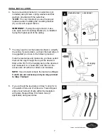
Install hanging ball of downrod (A) into opening of 
mounting bracket (C). Align one of the slots in 
hanging ball with the tab in mounting bracket (C). 


DANGER:

 Failure to align one of the slots in 

hanging ball with the tab in mounting bracket (C) 
may result in serious injury or death.

7. 


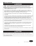
WARNING:

  To reduce the risk of fire, electrical shock or personal injury, each quick connect 

clip provided with this 

fan is designed to accept only one 12-gauge house wire and one lead wire 

from the fan. If your house wire is larger than 12-gauge or there is more than one house wire to 
connect to the corresponding fixture lead wires, consult an electrician. 


CAUTION:

 Be sure outlet box is properly grounded and that a ground (green or bare) wire is present.

       WARNING:

 The wires from the outlet box must be connected to a corresponding color of the 

fan's wires. Be sure wire colors match before making connections. If house wires are different 
colors than referred to in the following steps, stop immediately. A professional electrician is 
recommended to determine wiring.

WIRING

       WARNING

: Using a full range dimmer switch (not included) to control fan speed will cause 

a loud humming noise from fan. To reduce the risk of fire or electrical shock, do NOT use a full 
range dimmer switch to control fan speed.

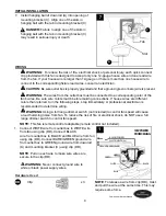
Connect WHITE wire from outlet box to WHITE wire 
from fan using clip (DD). Connect BLACK 
wire from outlet box to BLACK and BLUE wire from fan 
using clip (DD). Connect BARE/GREEN ground wire 
from outlet box to GREEN ground wire from downrod 
(A) and mounting bracket (C) using clip (DD).

NOTE

: Pull on each wire to make sure wires are 

secure in the clip (DD). 

 1. 

C

A

7

Slot

Tab


WARNING:

  Never connect ground wire to 

white or black power supply wires.

NOTE

: To release a wire from clip (DD), twist 

and pull the wire at the same time. This may 
require some force.

1

120V POWER 

FROM CEILING

GREEN

WHITE

BLACK

BLUE

BLACK (POWER)

WHITE (NEUTRAL) 

GROUND/GREEN (BARE)

DD

Clip                                                         x 3 

Hardware Used

NOTE:

 This fan is remote control adaptable (remote control not included). 

Summary of Contents for WINDRISE E-TLEII44BNK5C1

Page 1: ...ervice department at 1 800 643 0067 8 a m 6 p m EST Monday Thursday 8 a m 5 p m EST Friday ATTACH YOUR RECEIPT HERE Serial Number Purchase Date EB14741 1 Espa ol p 19 Lowes com harborbreeze Federal re...

Page 2: ...end of the blades to any obstruction After you install the fan make sure all connections are secure to prevent the fan from falling The net weight of this fan including the light kit is 16 53 lbs Saf...

Page 3: ...lead wires from the fan If your house wire is larger than 12 gauge or there is more than one house wire to connect to the corresponding fan lead wires consult an electrician for the proper size wire...

Page 4: ...ssembled K Hex Nut 2 preassembled L Lock Washer 1 preassembled DESCRIPTION PART QUANTITY M Switch Housing Cap 1 preassembled N Switch Housing Cap Screw 3 preassembled O Finial preassembled 1 P Glass S...

Page 5: ...n carpet or on foam to avoid damage to finish Compare parts with package contents list and hardware contents list If any part is missing or damaged do not attempt to install operate or assemble the pr...

Page 6: ...Check to make sure blades G will be at least 30 inches from any obstruction Check downrod A length to ensure blades G will be at least 7 ft above the floor 3 ON OFF ON OFF 1 2 Determine mounting metho...

Page 7: ...ry and you may proceed to Step 7 instead 5 4 If you cut back the lead wires in Step 5 strip 1 2 in of insulation from end of white wire Twist stripped ends of each strand of wire within the insulation...

Page 8: ...ections If house wires are different colors than referred to in the following steps stop immediately A professional electrician is recommended to determine wiring WIRING WARNING Using a full range dim...

Page 9: ...x from the black and blue connections Gently push wires and clips DD into outlet box 2 DD DD 2 DD 1 FINAL INSTALLATION B C Raise canopy B toward ceiling and allow it to attach to mounting bracket C us...

Page 10: ...cessed groove on the three C clips BB BB G Friction Detents Recessed Groove 4 X J J BB BB Three C clip x 3 Hardware Used NOTE To install the fan without the light kit proceed to INSTALLING FAN WITHOUT...

Page 11: ...rub against bulbs during fan operation Secure glass shade P with hex nut K CAUTION Do NOT overtighten hex nut K as glass may crack or break Then align hole in center of finial plate I with threaded r...

Page 12: ...p M Locate wires in switch housing labeled FOR LIGHT and gently pull molex connections apart in order to disconnect switch housing cap M from switch housing INSTALLING FAN WITHOUT LIGHT KIT FINAL INST...

Page 13: ...IT Attach applicable pull chain extension CC or custom pull chain extension not included to fan pull chain 4 4 Pull Chain Extension x 1 Hardware Used CC K Remove the hex nut K and lock washer L from t...

Page 14: ...nce in your comfort NOTE Wait for fan to stop before moving the reverse switch 3 14 Lowes com harborbreeze 3 OPERATING INSTRUCTIONS The fan pull chain located on the switch housing of motor housing D...

Page 15: ...the middle position fan will not operate 3a 3b 3c At least twice each year lower canopy B to check downrod A assembly and then tighten all screws on fan Clean motor housing D with only a soft brush o...

Page 16: ...Set screw s on motor housing yoke is are not tightened properly 7 Set screw on hanging ball is not tightened properly 1 Tighten all blade screws 2 Re install blade arms 3 Switch one blade with a blade...

Page 17: ...ic conditions this warranty does not cover changes in brass finish rusting pitting tarnishing corroding or peeling Brass finish fans maintain their beauty when protected from varying weather condition...

Page 18: ...Printed in China REPLACEMENT PARTS LIST For replacement parts call our customer service department at 1 800 643 0067 8 a m 6 p m EST Monday Thursday 8 a m 5 p m EST Friday NOLI1412 Harbor Breeze is a...

Page 19: ...EXPLODED VIEW VISTA DETALLADA A E D B H C G L K I F M Q P N O R AA BB CC DD QUICK REFERENCE GUIDE GU A DE REFERENCIA R PIDA J S V W T U...

Page 20: ...ion Este es un resumen general del proceso de ensamblaje Lea el manual de instalaci n completo para obtener instrucciones detalladas e informaci n de seguridad Downrod Standard Downrod Angled Ceiling...

Page 21: ...EN NGULO Attach Canopy K N B C Magnet Im n Install Without Light Kit Install without light kit Install Pull Chain Extensions H CC CC CC WITHOUT LIGHT KIT WITH LIGHT KIT CON EL KIT DE ILUMINACI N SIN E...

Page 22: ...ian if wiring needs differ Green Verde Green Verde Green Verde White Blanco White Blanco White Blanco Black Negro Black Negro Ground Tierra From Power Source From Power Source Blue Azul See Page Consu...

Page 23: ...7 de lunes a jueves de 8 a m a 6 p m y los viernes de 8 a m a 5 p m hora est ndar del Este ADJUNTE SU RECIBO AQU N mero de serie Fecha de compra 19 Lowes com harborbreeze Los reglamentos federales req...

Page 24: ...spas est n como m nimo a 76 2 cm de cualquier obst culo Una vez instalado el ventilador aseg rese de que todas las conexiones sean seguras a fin de evitar que se caiga El peso neto de este ventilador...

Page 25: ...ador Si el cable de la casa es de un calibre superior a 12 o hay m s de un cable para conectar a los cables conductores del ventilador correspondientes consulte a un electricista cu l es el tama o ade...

Page 26: ...onal 2 preensamblada L Arandela de seguridad 1 preensamblada DESCRIPCI N PIEZA CANTIDAD M Tapa de la carcasa del 1 interruptor preensamblada N Tornillo de la tapa de la carcasa del interruptor 3 preen...

Page 27: ...ombra o espuma para evitar da ar el acabado Compare las piezas con la lista del contenido del paquete y la lista de aditamentos No intente instalar usar ni ensamblar el producto si falta alguna pieza...

Page 28: ...tar n al menos a 76 2 cm de cualquier obst culo Verifique el largo de la varilla A para asegurarse de que las aspas G estar n al menos a 2 13 m por encima del piso 3 ON OFF ON OFF 1 2 Determine el m t...

Page 29: ...Si cort los cables conductores en el Paso 5 pele 12 70 mm del aislamiento en el extremo del cable blanco Tuerza los extremos pelados de cada filamento de cable dentro del aislamiento con pinzas Repit...

Page 30: ...siguientes pasos det ngase de inmediato Se recomienda que un electricista profesional determine el cableado adecuado CABLEADO ADVERTENCIA El uso de un regulador de intensidad de rango completo no se i...

Page 31: ...bles y los sujetadores DD hacia la caja de salida 2 DD DD 2 DD 1 INSTALACI N FINAL B C Levante la base B hacia el techo y deje que se fije a la abrazadera de montaje C con los imanes que se encuentran...

Page 32: ...de fricci n Ranura empotrada 4 X J J BB BB Sujetador triple C x 3 Aditamentos utilizados NOTA Si desea instalar el ventilador sin el kit de iluminaci n contin e con INSTALACI N DEL VENTILADOR SIN EL...

Page 33: ...ador est funcionando Asegure la pantalla de vidrio P con la tuerca hexagonal K PRECAUCI N NO apriete demasiado la tuerca hexagonal K ya que podr a agrietar o quebrar el vidrio Luego alinee el orificio...

Page 34: ...interruptor etiquetados como FOR LIGHT PARA LA LUZ y separe suavemente las conexiones molex para desconectar la tapa M de la carcasa del interruptor INSTALACI N DEL VENTILADOR SIN EL KIT DE ILUMINACI...

Page 35: ...n para la cadena de tiro CC que corresponda o la extensi n para las cadenas de tiro personalizadas no se incluyen a la cadena de tiro del ventilador 4 Extensi n para x 1 la cadena de tiro Aditamentos...

Page 36: ...de mover el interruptor de reversa 3 32 Lowes com harborbreeze INSTRUCCIONES DE FUNCIONAMIENTO La cadena de tiro del ventilador ubicada en la carcasa del interruptor de la carcasa del motor D tiene c...

Page 37: ...el medio el ventilador no funcionar 3a 3b 3c Al menos dos veces al a o baje la base B para revisar el ensamble de la varilla A y luego apriete todos los tornillos en el ventilador Limpie la carcasa de...

Page 38: ...l los tornillo s de fijaci n en la horquilla de la carcasa del motor no est n bien apretado s 7 El tornillo de fijaci n en la bola para colgar no est bien apretado 1 Apriete todos los tornillos de las...

Page 39: ...antes esta garant a no cubre cambios en el acabado de lat n xido picaduras deslustre corrosi n o descascarado Los ventiladores con acabado de lat n mantienen su belleza cuando se les protege de las co...

Page 40: ...S DE REPUESTO Para obtener piezas de repuesto llame a nuestro Departamento de Servicio al Cliente al 1 800 643 0067 de lunes a jueves de 8 a m a 6 p m y los viernes de 8 a m a 5 p m hora est ndar del...

Reviews: