background image

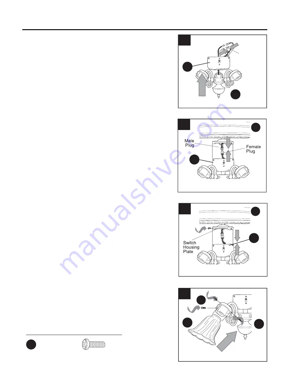
Align holes in switch housing (E) with holes in 
switch housing plate

Re-insert screws that were 

removed in Step 4 on the previous page, and 
then tighten all screws securely. (Fig. 8)

Note:


If you are not using the light kit

, please 

proceed to Step 11 

instead

 of continuing with 

Step 9.

D

7

FINAL INSTALLATION

 6. 

 7. 

 8. 

8

13

9. 

BB

AA

Connect male plug from motor housing (D) to 
female plug from switch housing (E). Make sure 
that plugs connect securely. (Fig. 7)

Connect 

WHITE

 wire from light kit fitter (F) to 

WHITE


wire from switch housing (E). Connect 

BLACK

 wire 

from light kit fitter (F) to 

RED

 wire from switch 

housing (E). Make sure that molex connections are 
secure. (Fig. 6)

6

F

E

Molex

Connections

E

9

D

E

Attach glass shade (I) using thumb screws (DD) 
provided in one of the hardware packs. (Fig. 9)

Note

: Do NOT overtighten thumb screws (DD) as 

glass may crack or break.

F

I

DD

Hardware Used

   Thumb Screw                          x 12 

DD

Summary of Contents for SHREVEPORT E-NO52AB5C4

Page 1: ...gistered trademark of LF LLC All Rights Reserved Espa ol p 19 ATTACH YOUR RECEIPT HERE Serial Number Purchase Date 1 Federal regulations require ceiling fans with light kits manufactured or imported a...

Page 2: ...SI NFPA 70 1999 Hire a qualified electrician or consult a do it yourself wiring handbook available at Lowe s if you are unfamiliar with installing electrical wiring Make sure the installation site you...

Page 3: ...To avoid personal injury the use of gloves may be necessary while handling fan parts with sharp edges To reduce the risk of fire electrical shock or personal injury wire connectors provided with this...

Page 4: ...ounting Bracket 1 D Motor Housing 1 E Switch Housing 1 F Light Kit Fitter 1 G Blade 5 H Blade Arm 5 I Glass Shade 4 A E D B F C K J G H P L O N I M PART DESCRIPTION QUANTITY J Motor Screw preassembled...

Page 5: ...e at Lowe s and Wire Cutters Bulbs Required included 4 candelabra base 40 watt max bulbs DANGER When using an existing outlet box make sure the outlet box is securely attached to the building structur...

Page 6: ...ling angle is not steeper than 19 2 2 Check to make sure blades G are at least 30 in from any obstruction Check downrod A length to ensure blades G are at least 7 ft above the floor Fig 3 3 G 3 Secure...

Page 7: ...g yoke at top of motor housing D and partially loosen set screws Fig 1 Helpful Hint Downrod style mounting is best suited for ceilings 8 ft 2 44 m high or higher For taller ceilings you may want to us...

Page 8: ...s Fig 4 Note If you do not cut back the lead wires Steps 4 and 5 are not necessary and you may proceed to Step 6 instead If you decided to cut back the lead wires in Step 4 strip 1 2 in of insulation...

Page 9: ...housing D on the tab on the mounting bracket C using one of the non slotted holes in the canopy B Fig 4 Tab C 4 4 WIRING WARNING To reduce the risk of fire electrical shock or personal injury wire con...

Page 10: ...EN wire from ceiling Fig 1B 1C FAN AND LIGHT CONTROLLED BY TWO WALL SWITCHES If you intend to control the fan and light with separate wall switches connect BLACK wire from fan to BLACK wire from the i...

Page 11: ...round each individual wire connector CC down to the wire as shown in Fig 2 WARNING Make sure no bare wire or wire strands are visible after making connections Place green and white connections on oppo...

Page 12: ...oceeding with the next Remove three screws from switch housing plate on underside of motor Fig 4 If you wish to use the light kit punch center cap out of switch housing E with a screwdriver Locate RED...

Page 13: ...from motor housing D to female plug from switch housing E Make sure that plugs connect securely Fig 7 Connect WHITE wire from light kit fitter F to WHITE wire from switch housing E Connect BLACK wire...

Page 14: ...ed in one of the hardware packs or custom pull chain extensions sold separately may be attached to fan and light pull chains Fig 11 Note This fan is remote control adaptable remote control sold separa...

Page 15: ...an help move stagnant hot air off the ceiling area Fig 3B 3A 3B 3C OPERATION INSTRUCTIONS 3C IMPORTANT Reverse switch must be set either completely UP or completely DOWN for fan to function If the rev...

Page 16: ...od of a few days especially when running the fan at Medium and High speeds Excessive wobbling 1 Blades G are loose 1 Tighten all blade screws AA 2 Blade arms H incorrectly 2 Re install blade arms H at...

Page 17: ...chase All cost of removal and reinstallation are the express responsibility of the purchaser Any damage to the ceiling fan by accident misuse or improper installation or by using parts not produced by...

Page 18: ...Screw BB Fiber Blade Washer CC E3 Wire Connector DD Thumb Screw EE Hex Nut FF Lock Washer Printed in China 18 REPLACEMENT PARTS LIST For replacement parts call our customer service department at 1 800...

Page 19: ...os derechos reservados ADJUNTE SU RECIBO AQU N mero de serie Fecha de compra LISTED 19 Los reglamentos federales requieren que los ventiladores de techo con kit de iluminaci n fabricados o importados...

Page 20: ...no est familiarizado con la instalaci n del cableado el ctrico contrate a un electricista calificado o consulte un manual de cableado disponible en Lowe s para hacerlo usted mismo Aseg rese de que el...

Page 21: ...ones personales puede ser necesario usar guantes al manipular las piezas del ventilador con bordes filosos Para reducir el riesgo de incendios descargas el ctricas o lesiones personales los conectores...

Page 22: ...l motor 1 E Carcasa del interruptor 1 F Soporte del kit de iluminaci n 1 G Aspa 5 H Brazo del aspa 5 I Pantalla de vidrio 4 A E D B F C K J G H P L O N I M PIEZA DESCRIPCI N CANTIDAD J Tornillo del mo...

Page 23: ...illas requeridas se incluyen 4 bombillas de base candelabro de 40 vatios como m ximo PELIGRO Si utiliza una caja de salida existente aseg rese de que est bien sujeta a la estructura del edificio y que...

Page 24: ...tenga una inclinaci n superior a los 19 2 2 Verifique que las aspas G est n al menos a 76 20 cm de cualquier obstrucci n Verifique el largo de la varilla A para asegurarse de que las aspas G est n al...

Page 25: ...r de la carcasa del motor D y afloje parcialmente los tornillos de fijaci n Fig 1 Consejo til El montaje de varilla es mejor para los techos de 2 44 m 8 pies o m s de alto Para techos m s altos le rec...

Page 26: ...ort los cables conductores los Pasos 4 y 5 no son necesarios y puede proceder con el Paso 6 en su lugar Si decidi cortar los cables conductores en el Paso 4 pele 1 27 cm del aislamiento del extremo de...

Page 27: ...a leng eta de la abrazadera de montaje C con uno de los orificios sin ranura de la base B Fig 4 Leng eta C 4 4 CABLEADO ADVERTENCIA Para reducir el riesgo de incendios descargas el ctricas o lesiones...

Page 28: ...ARED Si desea controlar el ventilador y la luz con interruptores de pared separados conecte el conductor NEGRO del ventilador al conductor NEGRO del interruptor de pared independiente para el ventilad...

Page 29: ...del cable como se muestra en la Fig 2 ADVERTENCIA Aseg rese de que no haya conductores desnudos ni filamentos de conductores visibles despu s de hacer la conexi n Coloque las conexiones verdes y blanc...

Page 30: ...tor en la parte inferior de la carcasa del motor Fig 4 Si desea usar el kit de iluminaci n perfore la cubierta central de la carcasa del interruptor E con un destornillador Ubique los conductores ROJO...

Page 31: ...os enchufes est n bien conectados Fig 7 Conecte el conductor BLANCO de la carcasa del interruptor F al conductor BLANCO del soporte del kit de iluminaci n E Conecte el conductor NEGRO de la carcasa de...

Page 32: ...nas de tiro a medida se venden por separado se pueden fijar a las cadenas de tiro del ventilador y la luz Fig 11 Nota Este ventilador es adaptable para control remoto el control remoto se vende por se...

Page 33: ...del techo Fig 3B 3A 3B 3C INSTRUCCIONES DE FUNCIONAMIENTO 3C IMPORTANTE El interruptor de reversa se debe configurar ya sea completamente HACIA ARRIBA o completamente HACIA ABAJO para que funcione el...

Page 34: ...las aspas H 3 Intercambie un aspa G con otra del lado opuesto 4 Desconecte la alimentaci n Afloje cuidadosamente la base B y verifique que la abrazadera de montaje C est asegurada 5 Utilice una varil...

Page 35: ...que podamos reparar o reemplazar el ventilador de techo Un ventilador o piezas devueltas con un embalaje incorrecto son de responsabilidad nica del comprador No existe otro tipo de garant a expl cita...

Page 36: ...dela para aspa de fibra CC Conector de cables E3 DD Tornillo de mariposa EE Tuerca hexagonal FF Arandela de seguridad Impreso en China 36 LISTA DE PIEZAS DE REPUESTO Para obtener piezas de repuesto ll...

Reviews: