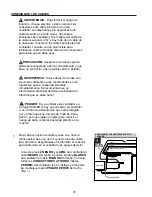
Align holes in switch housing (E) with holes in
fitter plate. Re-insert screws that were removed in
the previous step and tighten all screws securely.
(Fig. 7)
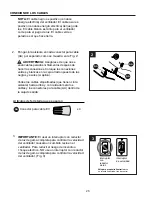
Attach pull chain extension (O) supplied in
one of the hardware packs or custom pull
chain extension (sold separately) to fan pull
chain. (Fig. 8)
NOTE:
This fan is remote control adaptable
(remote control sold separately). Any remote
control used with this fan MUST be
UL-approved for DAMP LOCATIONS.
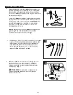
Remove three screws from fitter plate on
underside of motor housing (D). Connect male
plug from motor housing (D) to female plug from
switch housing (E). (Fig. 6) Make sure plugs
connect tightly.
Fitter
Plate
Female
Plug
Male Plug
FINAL INSTALLATION
D
D
E
E
6
D
7
Fitter
Plate
E
8
O
8.
7.
6.
12


