background image

9

Lowes.com/harborbreeze

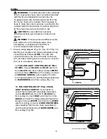
NOTE:

 Black wire is hot power for fan. Blue wire is 

hot power for light kit. White wire is common for fan 
and light kit. Green or bare wire is ground.

WIRING

1C. 

FAN AND LIGHT CONTROLLED BY TWO 

WALL SWITCHES:

 If you intend to control the fan 

and light with separate wall switches, connect 

BLACK

 wire from fan to 

BLACK

 wire from the 

independent wall switch for the fan. Connect 

BLUE

 wire from fan to the 

BLACK

 wire from the 

other independent wall switch for the light. 
Connect 

WHITE

 wire from fan to 

WHITE

 wire 

from ceiling. Connect all 

GROUND

 (

GREEN

wires together from fan (on motor assembly (C) 
and mounting bracket (A)) to 

BARE

/

GREEN

 wire 

from ceiling. (Fig. 1C)

Wrap electrical tape (not included) around each 
individual wire connector (CC) down to the wire.


WARNING:

  Make sure no bare wire or wire 

strands are visible after making connections. Place 
green and white connections on opposite side of 
box from the black and blue (if applicable) 
connections.

Turn spliced/taped wires upward and gently push 
wires and wire connectors (CC) into outlet box.

 2. 

 2. 

CC

2

CC

CC

1C

FAN AND LIGHT CONTROLLED BY TWO WALL SWITCHES

WHITE

BLACK (WALL SWITCH)

(WALL SWITCH FOR LIGHT)

GROUND/GREEN (BARE)

BLACK

BLUE

WHITE

FROM FAN

120 V Power 

FROM

CEILING

GREEN

WHITE

GREEN

FAN

BLACK

Hardware Used

E3 Wire Connector

x 4

CC

Summary of Contents for BTH44ABZC5C

Page 1: ...44ABZC5C BTH44BNK5C Questions problems missing parts Before returning to your retailer call our customer service department at 1 800 643 0067 8 a m 6 p m EST Monday Thursday 8 a m 5 p m EST Friday ATT...

Page 2: ...factory for repairs it must be shipped in its original packaging to ensure proper protection against damage that might exceed the initial cause for return Make sure that all electrical connections com...

Page 3: ...gned to accept only one 12 gauge house wire and two lead wires from the fan If your house wire is larger than 12 gauge or there is more than one house wire to connect to the corresponding fan lead wir...

Page 4: ...3 DESCRIPTION PART QUANTITY N Motor Screw 10 preassembled 1 extra O 5 4 mm Lock Washer 10 preassembled 1 extra P Hex Nut preassembled 1 Q Lock Washer 1 preassembled R Mounting Bracket Screw 4 preasse...

Page 5: ...let box is securely attached to the building structure and can support the full weight of the fan Failure to do this can result in serious injury or death The stability of the outlet box is essential...

Page 6: ...ashers and flat washers provided with the outlet box Pull wires from outlet box through center hole in mounting bracket A NOTE It is very important that you use the proper hardware when installing the...

Page 7: ...stic lock tab L Slide plastic lock tab L under bracket tabs so that it will snap into place IMPORTANT Keep in mind that it will require some force to fully insert the plastic lock tab L so that it doe...

Page 8: ...nnector CC on in a clockwise direction 1A FAN AND LIGHT CONTROLLED BY PULL CHAINS Connect BLACK and BLUE wire from fan to BLACK wire from ceiling Connect WHITE wire from fan to WHITE wire from ceiling...

Page 9: ...l GROUND GREEN wires together from fan on motor assembly C and mounting bracket A to BARE GREEN wire from ceiling Fig 1C Wrap electrical tape not included around each individual wire connector CC down...

Page 10: ...two mounting bracket screws R Remove the other two mounting bracket screws R and star washers S Now lift motor housing B to mounting bracket A again aligning slotted holes in motor housing B with loo...

Page 11: ...rubber washer T for later use Continue to Step 5 If you do NOT wish to use the light kit please go to section titled Installing Fan Without Included Light Kit Optional on page 14 4 FINAL INSTALLATION...

Page 12: ...fit Re insert switch housing cap screws U that were removed in Step 4 on the previous page and use a Phillips screwdriver not included to secure all switch housing cap screws U 6 7 Install three cande...

Page 13: ...le in center of glass shade E with threaded rod on light kit fitter D allowing pull chains to come through corresponding holes in glass shade E Push up gently on glass shade E until threaded rod comes...

Page 14: ...ll be immediately installed and the power should be turned off prior to molex safety cap removal and light kit installation Switch Housing Cap WHITE BLACK 2 2 Locate cap K in one of the hardware packs...

Page 15: ...The pull chain located in the center is used to turn the light ON or OFF 2 1 2 3 Use the fan reverse switch located on the switch housing to optimize your fan for seasonal performance A ceiling fan w...

Page 16: ...use water or a damp cloth to clean the ceiling fan 16 CARE AND MAINTENANCE OPERATING INSTRUCTIONS Lowes com harborbreeze 3A 3B 3C 3C IMPORTANT Reverse switch must be set either completely UP or comple...

Page 17: ...bracket A is secure according to instructions on page 10 Excessive wobbling 1 Blades G are loose 2 Blade arms J incorrectly attached 3 Unbalanced blades G 4 Fan not securely mounted 1 Tighten all bla...

Page 18: ...y does not cover changes in brass finish rusting pitting tarnishing corroding or peeling Brass finish fans maintain their beauty when protected from varying weather conditions Any glass provided with...

Page 19: ...s Shade F Pull Chain Extension G Blade H Finial Plate I Finial J Blade Arm K Cap L Plastic Lock Tab N Motor Screw O 5 4 mm Lock Washer P Hex Nut Q Lock Washer R Mounting Bracket Screw S Star Washer T...

Reviews: