background image

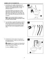
Depending on the length of downrod you use, 
you may need to cut the lead wires back to 
simplify the wiring. If you decide to cut back the 
lead wires, it is suggested you do so in the 
following manner:

Take the lead wires and make sure you have 
pulled them all the way through the top of the 
downrod (A). Start at the TOP of the ball on the 
downrod (A) and measure 8 in. of lead wire, and 
then cut the excess wire off with wire cutters (not 
included). 

NOTE:

 If you do 

not

 cut back the lead wires, 

Steps 4 and 5 are not necessary and you may 
proceed to Step 6 instead

.

 4. 

Ball

 5. 

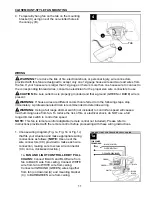
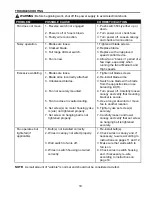
Install ball end of downrod (A) into opening of 
mounting bracket (C). Align slot in ball with tab in 
mounting bracket (C). 


DANGER:

 Failure to align slot in ball with tab 

may cause the fan to wobble or fall, which could 
result in serious injury or death.

6. 

Continue to 

WIRING

 on page 11.

C

DOWNROD-STYLE FAN MOUNTING

4

9

5

6

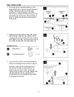
If you decided to cut back the lead wires in Step 4, 
strip 1/2 in. of insulation from end of white wire. 
Twist stripped ends of each strand of wire within 
the insulation with pliers (not included). Repeat 
Step 5 for black, blue (if applicable) and green 
wires.

Slot

A

A

Tab

Summary of Contents for BDB52BNK5L

Page 1: ...BAY CEILING FAN Espa ol p 20 1 MODEL BDB52BNK5L BDB52OSB5L ATTACH YOUR RECEIPT HERE Serial Number Purchase Date Questions problems missing parts Before returning to your retailer call our customer ser...

Page 2: ...e factory for repairs it must be shipped in its original packaging to ensure proper protection against damage that might exceed the initial cause for return Make sure all electrical connections comply...

Page 3: ...or electrical shock do not use the fan with any solid state speed control device or control fan speed with a full range dimmer switch To reduce the risk of fire electrical shock or personal injury do...

Page 4: ...MINDER You must use the parts provided with this fan for proper installation and safety PACKAGE CONTENTS 4 A Downrod 1 B Canopy 1 C Mounting Bracket 1 preassembled D Motor Housing 1 E Glass Shade 4 F...

Page 5: ...inish Compare parts with package contents list and hardware contents list If any part is missing or damaged do not attempt to install operate or assemble the product Estimated Assembly Time 120 minute...

Page 6: ...check to make sure the ceiling angle is not steeper than 19 Helpful Hint Downrod style mounting is best suited for ceilings 8 ft or higher For taller ceilings you may want to use a longer downrod not...

Page 7: ...n 19 4b INITIAL INSTALLATION 7 5 Remove motor screws I and lock washers K from underside of motor housing D If there are plastic motor blocks installed with the motor screws I and lock washers K disca...

Page 8: ...8 3 1 Slip downrod A into yoke align holes and re install pin M and clip N Tighten set screws in yoke and then tighten nut and set screws Set Screw and Nut B A 2 Remove pin M and clip N from downrod A...

Page 9: ...e lead wires Steps 4 and 5 are not necessary and you may proceed to Step 6 instead 4 Ball 5 Install ball end of downrod A into opening of mounting bracket C Align slot in ball with tab in mounting bra...

Page 10: ...The downrod A and canopy cover are not used in this type of installation 1 Remove every other preassembled screw and lock washer from top of motor housing D 2 3 CLOSEMOUNT STYLE FAN MOUNTNG 10 Pull wi...

Page 11: ...ke appropriate wiring connections as follows NOTE Use one of the wire connectors CC provided to make each wire connection making sure to screw wire connector CC on in a clockwise direction 1a FAN AND...

Page 12: ...to WHITE wire from ceiling Connect all GROUND GREEN wires together from fan on downrod A and mounting bracket C to BARE GREEN wire from ceiling 1c FAN AND LIGHT CONTROLLED BY TWO WALL SWITCHES If you...

Page 13: ...holes in canopy B with loosened canopy mounting screws L in mounting bracket C Twist canopy B to lock then insert the two canopy mounting screws L and star washers O previously removed Step 4a page 7...

Page 14: ...switch housing for the correct fit 5 14 4 Remove three preassembled light kit fitter screws P from light kit fitter Q Locate BLUE or BLACK and WHITE wires in switch housing preassembled on motor housi...

Page 15: ...from sockets on light kit fitter Q Attach glass shades E to sockets securing with socket rings R WARNING Do not overtighten socket rings R as glass may crack or break 7 7 Q E R J 9 Attach pull chain e...

Page 16: ...wo is MEDIUM three is LOW and four turns the fan OFF 1 Switch Housing 1 2 3 Use the fan reverse switch located on the switch housing to optimize your fan for seasonal performance A ceiling fan will al...

Page 17: ...t use water or a damp cloth to clean the ceiling fan Bulb Replacement Use standard base 6 5 watt LED bulbs or 13 watt CFLs or 40 watt max incandescent bulbs CARE AND MAINTENANCE 3A In warmer weather s...

Page 18: ...yoke is are not tightened properly 7 Set screw on hanging ball is not tightened properly 1 Tighten all blade screws 2 Re install blade arms 3 Switch one blade with a blade from the opposite side or u...

Page 19: ...ny glass provided with this fan is not covered by the warranty Any replacement of defective parts for the ceiling fan must be reported within the first year from the date of purchase For the balance o...

Reviews: