Hapton Bay Seaport Owner'S Manual Download Page 15

12

Specifications

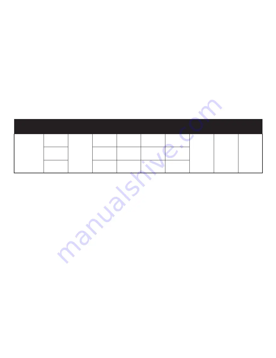
FAN SIZE SPEED VOLTS AMPS WATTS RPM

CFM

N.W.

G.W.

C.F.

52”

120

10.18 kgs

(22.40 lbs)

11.21 kgs

(24.66 lbs)

1.77'

LOW

MED.

HIGH

0.21

0.35

0.46

11

31

55

67

118

159

1891

3408

5020

These are approximate measures. They do not include Amps and Wattage used by the light kit.

Summary of Contents for Seaport

Page 1: ...Seaport 52 in Ceiling Fan Owner s Manual Seaport Ventilador de Techo de 1 32 m Manual del Propietario 513 349 ...

Page 2: ...Seaport by Hampton Bay ...

Page 3: ...ling the Light Kit 9 Operating Your Fan 10 Care of Your Fan 11 Troubleshooting 11 Specifications 12 Warranty Information 13 513 349 792145356165 11289 UL Model No Thank you for purchasing our ceiling fan This product has been manufactured with the highest standards of safety and quality The finish of this fan is weather resistant but over time will naturally weather and fade ...

Page 4: ...ades To avoid personal injury or damage to the fan and other items be cautious when working around or cleaning the fan Do not use water or detergents when cleaning the fan or fan blades A dry dust cloth or lightly dampened cloth will be suitable for most cleaning After making electrical connections spliced conductors should be turned upward and pushed carefully up into outlet box The wires should ...

Page 5: ...5 Mounting plate Light plate Glass shade decorative frame assembly 13 watt compact fluorescent bulbs 2 Pull chains and fobs 2 6 7 8 9 10 11 WARNING DO NOT INSTALL OR USE FAN IF ANY PART IS DAMAGED OR MISSING CALL TOLL FREE 1 877 902 5588 1 2 6 5 8 9 10 11 7 3 4 Blade Attachment Hardware 16 Screws with Rubber Washers Electrical Hardware 3 Plastic Wire Nuts Light Kit Hardware 4 Screws Balance Kit A ...

Page 6: ...G SCREWS PROVIDED WITH THE OULET BOX OUTLET BOX COMMONLY USED FOR THE SUPPORT OF LIGHTING FIXTURE MAY NOT BE ACCEPTABLE FOR FAN SUPPORT AND MAY NEED TO BE REPLACED CONSULT A QUALIFIED ELECTRICIAN IF IN DOUBT Outlet Box Outlet Box Outlet Box Figure 2 Figure 1 Note You may need a longer downrod to maintain proper blade clearance when installing on a steep sloped ceiling The maximum angle allowable i...

Page 7: ...mounting bracket from the canopy by removing the 1 of 2 screws from the bottom of the mounting bracket and loosening the other one a half turn from the screw head Next turn the canopy counter clockwise to removing the mounting bracket from the canopy Figure 5 Remove the clevis pin cotter pin and set screws from the top of the motor assembly Figure 6 NOTE If a longer downrod is needed take out the ...

Page 8: ...EAT THE TAB IN THE GROOVE COULD CAUSE DAMAGE TO WIRING Pass the 120 volt supply wires through the center hole in the ceiling mounting bracket as shown in Figure 7 Install the ceiling mounting bracket on the outlet box with the screws and washers provided with your outlet box Figure 7 Security tighten the two mounting screws Carefully lift the fan assembly up to the ceiling mounting bracket and sea...

Page 9: ...ound conductor of the 120V supply this may be a bare wire or a wire with green colored insulation to the green ground lead s of the fan Figure 9 Connect the fan motor white wire to the supply white neutral wire using a wire nut Figure 9 Connect the fan motor black wire to the supply black hot wire using a wire nut Figure 9 Connect the blue wire for light kit to the black household supply wire 1 2 ...

Page 10: ... Outlet Box Ceiling Mounting Bracket Screw Screw Canopy Canopy Bottom Cover Attaching the Fan Blades Attach blades to blade arm using the screws with rubber washers provided Fig 11 Start a screw into the blade arm do not tighten Repeat for the 2 remaining screws and washers Tighten each screw securely starting with the center screw Make sure the blade is straight Repeat steps for the remaining bla...

Page 11: ...hould be within 1 8 Run the fan for 10 Minutes Use the enclosed Blade Balancing Kit if the blade wobble is still noticeable 1 2 3 The following procedure should correct most fan wobble Check after each step Touching Ceiling Figure 14 Installing the Mounting Plate Remove 1 of 3 screws from the mounting ring and loosen the other 2 screws Do not remove Place the key holes on the mounting plate over t...

Page 12: ...ng screws previously loosened and the one previously removed Fig 15 Install two 13 watt compact fluorescent bulbs included to the light sockets Raise the glass shade decorative frame assembly up against bottom of light kit align 1 2 3 4 5 CAUTION BEFORE STARTING INSTALLATION DISCON NECT THE POWER BY TURNING OFF THE CIRCUIT BREAKER OR REMOVING THE FUSE AT FUSE BOX TURNING POWER OFF USING THE FAN SW...

Page 13: ...ting unit on a lower setting without affecting your comfort Turn on the power and check the operation of the fan The pull chain controls the fan speed as follows 1 pull High 2 pulls Medium 3 pulls Low 4 pulls Off Light kit pull chain it controls the light kit in ON or OFF Speed settings for warm or cool weather depend on factors such as the room size ceiling height number of fans and so on The sli...

Page 14: ...lication of shoe polish There is no need to oil your fan The motor has permanently lubricated sealed ball bearings 1 2 3 4 Here are some suggestions to help you maintain your fan Care of Your Fan Troubleshooting PROBLEM SOLUTION Fan will not start Fan sounds noisy Check main and branch circuit fuses or breakers Check line wire connections to the fan and switch wire connections in the switch housin...

Page 15: ...TS AMPS WATTS RPM CFM N W G W C F 52 120 10 18 kgs 22 40 lbs 11 21 kgs 24 66 lbs 1 77 LOW MED HIGH 0 21 0 35 0 46 11 31 55 67 118 159 1891 3408 5020 These are approximate measures They do not include Amps and Wattage used by the light kit ...

Page 16: ... should not be considered a defect Servicing performed by unauthorized persons shall render the warranty invalid There is no other express warranty Hampton Bay hereby disclaims any and all warranties including but not limited to Those of merchantability and fitness for a particular purpose to the extent permitted by law The duration of any implied warranty which cannot be disclaimed is limited to ...

Reviews: