66
FMS 1 - Fluorescence Monitoring System
© 2017 Hansatech Instruments Ltd
monitoring bar is displayed (
). A value of zero will be recorded for both parameters
if the leaf-clip electronics are
not connected to the control unit.
3.7.4
External Device Interface and Event Markers
The remaining buttons on the instrument toolbar control the external device interface and
application of user-specified event markers.
3.7.4.1
External Control Interface
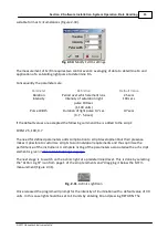
The FMS1 is provided with a digital control interface to aid interfacing of controls with third party
equipment. It is possible to trigger external devices which are connected to line 0 directly from the
instrument toolbar whilst experiments are being run using “O/P” button or during a script using
the DIGIT element (
Hansatech Scripting Language Elements
).
This approach is suitable for triggering an external device to log an event in parallel with FMS.
Conversely the FMS accepts up to four digital inputs which trigger the FMS in response to control
from an external device. The status of input lines 0 and 1 is shown on the instrument monitoring
bar during manual operation (B, Figure 2-1) and may be used to advance scripts that have been
paused using the WDON, WOFF elements (
Hansatech Scripting Language Elements
).
A digital to analogue (D/A) line is also provided for control of devices such as external LED light
sources which require variable voltage (0 to 4095 mV) control. The D/A line is toggled on / off
from the “DAC” button with required voltage output (in mV) set in the adjacent edit box. Control is
also possible during script operation using the DAC element with the required voltage as the
element parameter. N.B. A DAC value of 0 switches off the channel.
Utilisation of either DAC or digital control lines requires appropriate wiring connections between
instruments. Pin connections to the FMS are explained in
ended connector cable is also available upon request from Hansatech Instruments Ltd.
3.7.4.2
Event Markers
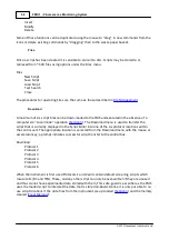
Whilst recording data all FMS-controlled illumination events are event-marked with coloured
arrows. The Up and Down arrow buttons on the instrument toolbar can be used to mark user-
specified events such as addition of herbicide or change of temperature etc. Each time one of the
event marker buttons is used an arrow is displayed above the data recording area and the
corresponding fluorescence data in the tabulated output is coloured-coded for easy retrieval. The
colour-codes may be customised to suit individual applications (
).
Summary of Contents for FMS1
Page 1: ......
Page 7: ...Section 1 Measurement Principles and Hardware ...
Page 21: ...Section 2 Software Installation System Operation Data Handling ...
Page 70: ...70 FMS 1 Fluorescence Monitoring System 2017 Hansatech Instruments Ltd ...
Page 71: ...Section 3 Stand Alone Instrument Operation and Data Upload ...
Page 83: ...83 Section 3 Stand Alone Instrument Operation and Data Upload 2017 Hansatech Instruments Ltd ...

