37
2020/09
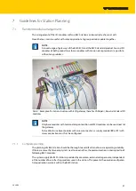
Cross-connecting relay module roots is achieved by the use of jumpers. The corresponding wiring
diagram including the jumpers can be found the manuals for BL20 I/O modules (German: D300716,
English: D300717).
7.2.5
Direct wiring of relay modules
As well as the options mentioned above, relay modules can be wired directly. In this case, base mod
-
ules without C-rail connections should be chosen to guarantee the potential isolation to the adjoin
-
ing modules.
7.3
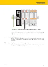
Protecting the service interface on the gateway
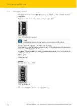
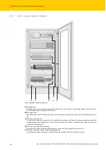
During operation, BL20 label protecting the service interface and the rotary coding switches must
remain in place due to EMC and ESD requirements.
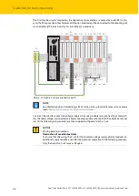
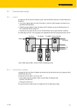
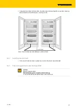
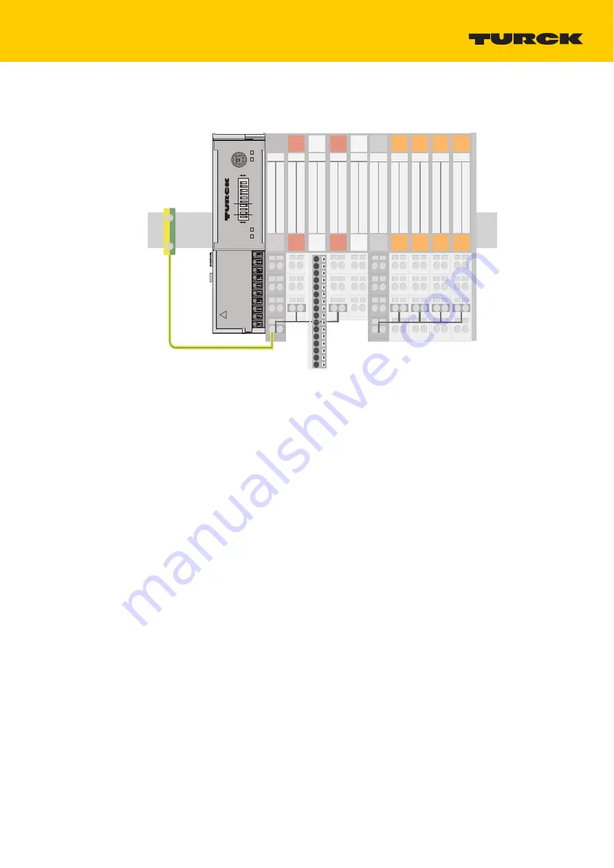
Abb. 5: Using the C-rail as protective earth and for the power supply with relay modules
23
22
21
13
12
11
23
23
22
22
21
21
13
13
12
12
11
11
24
23
22
21
14
13
12
11
TS
SBBC
2 DO
SBC
8 DI
ECO 2 DO
SBC
2 DI
SBB
C-rail (PE)
PE
terminal
PF
1
2
3
4
5
6
7
8
9
10
11
12
13
14
15
16
24
23
22
21
14
13
12
11
24
23
22
21
14
13
12
11
24
23
22
21
14
13
12
11
24
23
22
21
14
13
12
11
24
23
22
21
14
13
12
11
PF
NC
NO
SBCS
SBCS
NO
SBCS
NC
SBCS
C-rail (24 V DC)
SBBC
Unlock end-bracket befor
e dismounting
Pull barrier for configuration and service
!
UL
GNDL
USYS
GNDSYS
CAN_H
CAN_L
CAN_H
CAN_L
CANGND
CANGND
GW
IOs
BL20-E-GW-CO
SERVICE
1
0
ADDRESS
20
21
22
23
24
25
RT
ERR
Bus
off
on
BR
20
21
22
Summary of Contents for BL20-ECO
Page 1: ...Your Global Automation Partner BL20 E GW CO ECO Gateway for CANopen Instructions for Use...
Page 2: ...2 Hans Turck GmbH Co KG T 49 208 4952 0 F 49 208 4952 264 more turck com www turck com...
Page 6: ...Hans Turck GmbH Co KG T 49 208 4952 0 F 49 208 4952 264 more turck com www turck com 4...


