6
ASSEMBLY INSTRUCTIONS
Hardware Used
FF
Hardware Used
EE
Hardware Used
BB
DD
FF
1
2
3
TT
x 4
3/16 in. Stainless Screw
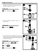
1. Attach post with burner assembly (G) onto heater
housing (H), using four 3/16 in. Stainless bolts (FF) .
Keep the access panel (D) open.
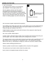
2.
Attach ring weight (F) to base (E) , using four
M6 X 20 bolts.
x 4
M6 X 20 Bolts
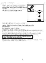
3. Put three reflector spacers (BB) into the holes in the
emitter (B). Use three nuts (DD) to hold the reflector
spacers inside of the emitter (B). Attach emitter (B) to
(G) using four bolts (FF).
x 3
Reflector spacers
x 3
Nuts
x 4
3/16 in. Stainless Screw
G
H
BB
B
DD
FF
G
E
F
EE
G
FF
D
H


