background image

User’s Manual 


ERROR MESSAGE & POSSIBLE SOLUTION 


CABLE NOT CONNECTED : 

1.  Check that the signal-cable is properly connected, If the connector is loose, tighten 

the connector’s screws. 

2.  Check the signal-cable’s connection pins for damage. 
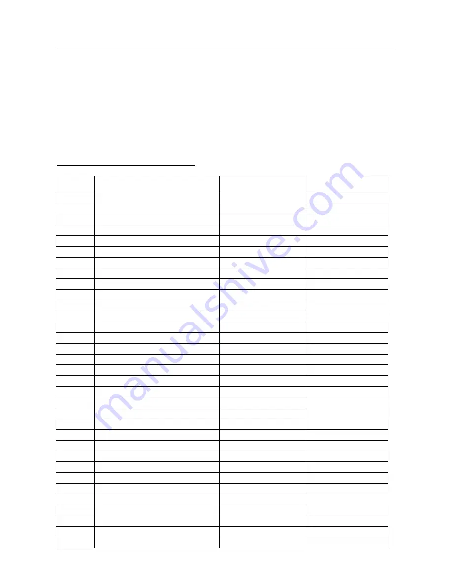


INPUT NOT SUPPORT : 

Your computer has been set to unsuitable display mode, set the computer to display 
mode given in the following table.   
 

FACTORY PRESET TIMING TABLE: 


MODE 

RESOLUTION 

HORIZONTAL 

FREQUENCY (KHz) 

VERTICAL 

FREQUENCY (Hz) 

1 640×350 

@70Hz 

31.469 

70.087 

2 640×400 

@56Hz 

24.827 

56.424 

3 640×400 

@70Hz 

31.469 

70.090 

4 640×480 

@60Hz 

31.469 

59.940 

5 640×480 

@67Hz 

35.000 

66.667 

6 640×480 

@72Hz 

37.861 

72.809 

7 640×480 

@75Hz 

37.500 

75.000 

8 720×400 

@70Hz 

31.469 

70.087 

9 800×600 

@56Hz 

35.156 

56.250 

10 800×600 

@60Hz 

37.879 

60.317 

11 800×600 

@72Hz 

48.077 

72.188 

12 800×600 

@75Hz 

46.875 

75.000 

13 832×624 

@74.6Hz 

49.725 

74.500 

14 1024×768 

@60Hz 

48.363 

60.004 

15 1024×768 

@66Hz 

53.964 

66.132 

16 1024×768 

@70Hz 

56.476 

70.069 

17 1024×768 

@75Hz 

60.023 

75.029 

18 1024×768 

@75Hz 

60.150 

74.720 

19 1152×864 

@75Hz 

67.500 

75.000 

20 1152×870 

@75Hz 

68.681 

75.062 

21 1152×900 

@66Hz 

61.846 

66.004 

22 1280×720 

@60Hz 

45.000 

60.000 

23 1280×768 

@60Hz 

47.776 

59.870 

24 1280×960 

@60Hz 

60.000 

60.000 

25 1280×1024 

@60Hz 

63.981 

60.020 

26 1280×1024 

@75Hz 

79.976 

75.025 

27 1360×768 

@60Hz 

47.712 

60.015 

28 1400×1050 

@60Hz 

64.744 

59.948 

29 1400×1050 

@60Hz 

65.317 

59.978 

30 1400×1050 

@75Hz 

82.278 

74.867 

31 1440×900 

@60Hz 

55.469 

59.901 

32 1440×900 

@60Hz 

55.935 

59.887 

33 1440×900 

@75Hz 

70.635 

74.984 

20 

Summary of Contents for HG191

Page 1: ...19 inch TFT LCD Monitor HG191 USER S MANUAL...

Page 2: ...ng the equipment off and on the user is encouraged to try to correct the interference by one or more of the following measures Reorient or relocate the receiving antenna Increase the separation betwee...

Page 3: ...rgy saving mode after a certain time beneficial both for the user and the environment Electrical safety Emissions Electromagnetic fields Noise emissions Ecology The product must be prepared for recycl...

Page 4: ...recycling of industrial technology devices at the end of life These devices contain recyclable materials which can be re decomposed and re integrated into brand new marvels On the contrary other mater...

Page 5: ...ACKAGE 8 INSTALLATION INSTRUCTIONS 9 POWER 9 CONTROLS AND CONNECTORS 10 ADJUSTING THE VIEWING ANGLE 11 OPERATING INSTRUCTIONS 12 GENERAL INSTRUCTIONS 12 FRONT PANEL CONTROL 13 HOW TO ADJUST A SETTING...

Page 6: ...he cabinet are provided for ventilation To ensure reliable operation of the monitor and to protect it from overheating be sure these openings are not blocked or covered Do not place the monitor on a b...

Page 7: ...use The LCD screen has effective pixels of 99 99 or more It may include blemishes of 0 01 or less such as a missing pixel or a pixel lit all of the time Due to the nature of the LCD screen an afterim...

Page 8: ...GY STAR Ergonomic Design Space Saving Compact Case Design CHECKING THE CONTENTS OF THE PACKAGE The product package should include the following items LCD Monitor Reference only the real feature is dep...

Page 9: ...ing sure that the clips are fully engaged in the base REMOVAL 1 Flip over the monitor so that it us upside down 2 Press the 1 clips that hold the monitor in place 3 Gently press and hold the 1 clips w...

Page 10: ...d of the 24 pin DVI D cable Dual input mode optional to the back of the monitor and connect the other end to the computer s DVI D port 3 Connect the audio cable between the monitor s audio input and t...

Page 11: ...the stand so you do not topple the monitor when you change the monitor s angle You are able to adjust the monitor s angle from 5 to 20 Figure 3 monitor s angle NOTES Do not touch the LCD screen when...

Page 12: ...anging these settings the picture can be adjusted to your personal preferences The power cord should be connected Connect the Signal cable from the monitor to the VGA card Press the power button to tu...

Page 13: ...ptimized the H Position V Position Clock and Focus NOTES Do not install the monitor in a location near heat sources such as radiators or air dusts or in a place subject to direct sunlight or excessive...

Page 14: ...Menu Enter the option and adjust the level How to adjust screen position and quality Select Image Setting on the Main Menu and then enter the option Horizontal position adjustment Select the H positi...

Page 15: ...of characters on the screen Enter the option and adjust the level How to adjust color Select the Color Setting option on the Main Menu and then enter the option Move the cursor to one of the preset o...

Page 16: ...n and adjust the level OSD vertical position adjustment Select the OSD V Position option to adjust the vertical position of the OSD Enter the option and adjust the level OSD timer setting Select the O...

Page 17: ...Enter the option and select a language Reference only the OSD Language is depended on selected model Volume adjustment Select the Volume option to change the volume level Enter the option and adjust...

Page 18: ...the DDC2B channel THIS MONITOR WILL APPEAR TO BE NON FUNCTIONAL IF THERE IS NO VIDEO INPUT SIGNAL IN ORDER FOR THIS MONITOR TO OPERATE PROPERLY THERE MUST BE A VIDEO INPUT SIGNAL This monitor meets th...

Page 19: ...ON position Computer Video Card should be snugly seated in its slot Make sure monitor s video cable is properly connected to the computer Inspect monitor s video cable and make sure none of the pins a...

Page 20: ...0 480 75Hz 37 500 75 000 8 720 400 70Hz 31 469 70 087 9 800 600 56Hz 35 156 56 250 10 800 600 60Hz 37 879 60 317 11 800 600 72Hz 48 077 72 188 12 800 600 75Hz 46 875 75 000 13 832 624 74 6Hz 49 725 74...

Page 21: ...W EPA ENERGY STAR OFF Mode 2 W Audio output Rated Power 1 5 W rms Per channel Input Connector D Sub 15pin DVI D 24pin Dual Input Model Maximum Screen Size Hor 408 24mm Ver 255 15mm Power Source 100 24...

Page 22: ...24 Pin Color Display Signal Cable Dual Input Mode PIN NO DESCRIPTION PIN NO DESCRIPTION 1 TMDS Data 2 13 TMDS Data 3 2 TMDS Data 2 14 5V Power 3 TMDS Data 2 4 Shield 15 Ground for 5V 4 TMDS Data 4 16...

Reviews: