


25
24
second is the integrative action and the third is the deriva-
tive action.
Proportional action can be set by means of the Proportional
Band (PB). Proportional Band is expressed in percentage of
the input range and is related to Kp according to the follow-
ing:
Kp = 100/PB.
The proportional action is set through the setup procedure
as “Deviation” in percent of full scale of the selected range.
Each setpoint has a selectable deviation: D1 for setpoint1
and D2 for setpoint2.
Two further parameters must be provided for both setpoints:
Ti
= Kp/Ki,
reset time
, measured in minutes
Td
= Kd/Kp,
rate time
, measured in minutes.
Ti1 and Td1 will be the reset time and rate time for setpoint1,
while Ti2 and Td2 will be the reset time and the rate time
for setpoint2.
TUNING A PID CONTROLLER
The proportional, integrative, derivative terms must be tuned,
i.e. adjusted to a particular process. Since the process vari-
ables are not typically known, a “trial and error” tuning
procedure must be applied to get the best possible control
for the particular process. The target is to achieve a fast
response time and a small overshoot.
Many tuning procedures are available and can be applied
to the EC/TDS controllers. A simple and profitable proce-
dure is reported in this manual and can be used in almost
all applications.
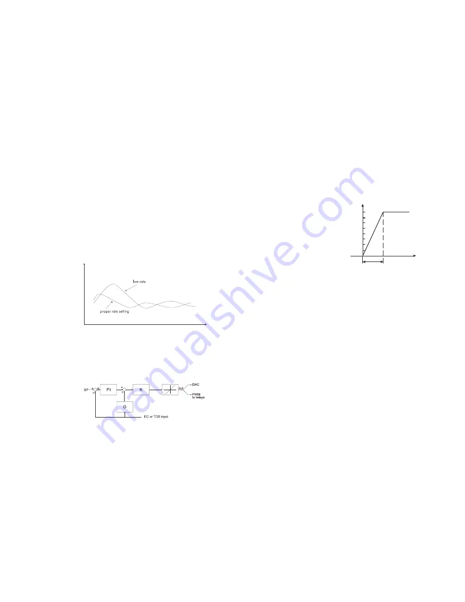
Error
100%
0
Proportional Band
Controller
output
The derivative function (rate action) compensates for rapid
changes in the system reducing undershoot and overshoot
of the EC or TDS value.
During PID control, the ON interval is dependent not only on
the error amplitude but even on the previous measurements.
Definitely PID control provides more accurate and stable
control than ON/OFF controllers and it is best suitable in
system with fast response, quickly reacting to changes due
to addition of low or high conductivity solution.
An example of how the response overshoot can be improved
with a proper rate action setting is depicted in the following
graphic.
PID TRANSFER FUNCTION
The transfer function of a PID control is as follows:
Kp + Ki/s + s Kd = Kp(1 + 1/(s Ti) +s Td)
with Ti = Kp/Ki, Td = Kd/Kp,
where the first term represents the proportional action, the
EC
RATE ACTION COMPENSATES FOR RAPID CHANGES
t


