background image

32

For those of you who are veterans of large models, this 

is old news. But to you newcomers to the world of large 

models, this is very important information.

Maintain the proper mechanical advantage on all 

control surface linkages.

Just as with unsealed hinge gaps, mechanical advantage 

is often another cause of flutter. Please follow the control 

horn and servo arm lengths recommended in this manual. 

Shorter arms on the servo or longer control horns on the 

elevator and ailerons are fine, but do not try to go the 

other way to increase throw. It can cause flutter or servo 

failure on the YAK 54. The recommended linkage setups 

are more than adequate to achieve full 3D throws.
Check the radio installation and make sure all the  

control surfaces are moving correctly (i.e. the correct 

direction and with the recommended throws). Test  

run the engine and make sure it transitions smoothly  

from idle to full throttle and back. Also ensure the  

engine is tuned according to the manufacturer’s 

instructions, and it will run consistently and constantly  

at full throttle when adjusted.
Check all the control horns, servo horns, and clevises to 

make sure they are secure and in good condition. Replace 

any items that would be considered questionable. Failure 

of any of these components in flight would mean the loss 

of your aircraft.
While many smaller models are very tolerant of improper 

control linkage setups and flying techniques, large models 

are not. Don’t let that scare you away from large models; 

they are truly one of the best flying experiences in RC that 

money can buy. However, please pay particular attention to 

the following areas.

Never attempt to make full throttle dives!

Large models perform much more like full-size aircraft 

than small models. If the airframe goes too fast, such as 

in a high throttle dive, it may fail. The YAK 54 should be 

flown like a full-scale YAK 54. Throttle management is 

absolutely necessary.

Hardware checks

Double-check the setscrews in all contol horns to be sure 

they are very tight. Periodically check these to be sure 

they have not loosened over time. Always use threadlock 

on metal-to-metal fasteners.

Receiver Battery Selection

Be sure adequate batteries are used to power the receiver. 

It is STRONGLY recommended that a 6-volt receiver pack 

is used. It must have a minimun of 2700mAh capacity.

Servo selection

Be sure all servos used on elevator, aileron and rudder are 

metal geared type and have at least 188 oz/in of torque. 

Failure to do this will very likely result in a failure and 

loss of the model.

Range check

Always range check the radio system per the 

manufacturer's instructions before the initial test flight and 

periodically afterward. 

Check the voltage of the on-board packs

ALWAYS use an ESV with a 1-amp load to check the 

receiver battery pack and the ignition pack before each 

and every flight. If there is any doubt that the packs are 

questionable, DO NOT FLY until the packs are recharged.

Preflight

Summary of Contents for YAK 54 89

Page 1: ...ngth w Spinner 84 in 213 4mm Wing Area 1434 sq in 92 8 sq dm Flying Weight 16 75 18 5 lb 7 6 8 4 kg Assembly manual YAK 54 89 Engine Size 45 60cc gas Radio 4 channels or more Servos 6 servos Hardware Included Yes Specifications ...

Page 2: ...ion and Repairs 6 Non Warranty Repairs 6 Safety Precautions and Warnings 7 Contents of Kit 7 Aileron Servo Installation 8 Rudder and Rudder Servo Installation 10 Tail Mounted Servo Installation 14 Stabilizer Servo and Installation 14 Landing Gear Installation 17 Engine Installation 20 Radio Installation 25 Pilot and Canopy Installation 27 Control Throws 29 Computer Radio Enhancements 29 Recommende...

Page 3: ...ch 3 32 inch 7 64 inch 1 8 inch Angle Pro Incidence Meter HAN192 Drill bit 1 16 inch 1 5mm 5 64 inch 2mm 5 32 inch 4mm 3 16 inch 4 5mm Adhesives Thin CA NHP411 Medium CA PAAPT02 30 Minute Epoxy HAN8002 Formula 560 Canopy Glue PAAPT56 CA Remover Debonder PAAPT16 Pacer Z 42 Threadlock PAAPT42 UltraCote Covering Colors White HANU870 Pearl Purple HANU847 Bright Yellow HANU872 Silver HANU881 Before Sta...

Page 4: ...mAh or larger for receiver 1500mAh or larger for ignition 4 8 or 6 0V for DA 50 2 cell Li Po for Evolution Gas engines The elevator installation will require Two servos and mixing through the radio Or Two servos and a JR MatchBox JPA0900 Recommended JR JRSPORT and Spektrum Systems JR 12X JR 10X JR XP9303 JR X9303 2 4 JR XP7202 Spektrum DX 7 Recommended Engine Setup DA 50 In cowl muffler or MTW 75K...

Page 5: ...o any part of the Product This warranty does not cover damage due to improper installation operation maintenance or attempted repair by anyone other than Horizon Return of any goods by Purchaser must be approved in writing by Horizon before shipment Damage Limits HORIZON SHALL NOT BE LIABLE FOR SPECIAL INDIRECT OR CONSEQUENTIAL DAMAGES LOSS OF PROFITS OR PRODUCTION OR COMMERCIAL LOSS IN ANY WAY CO...

Page 6: ...rranty Inspection and Repairs To receive warranty service you must include your original sales receipt verifying the proof of purchase date Provided warranty conditions have been met your Product will be repaired or replaced free of charge Repair or replacement decisions are at the sole discretion of Horizon Hobby Non Warranty Repairs Should your repair not be covered by warranty the repair will b...

Page 7: ...t chargers rechargeable battery packs etc that you use Keep all chemicals small parts and anything electrical out of the reach of children Moisture causes damage to electronics Avoid water exposure to all equipment not specifically designed and protected for this purpose Contents of Kit Replacement Parts A HAN4651 Fuselage w Hatch B HAN4652 Right Wing Panel w Aileron C HAN4653 Left Wing Panel w Ai...

Page 8: ...tional Step 1 Thread the control horn onto the threaded rod The distance between the aileron and the bottom of the horn is 27 32 inch 21 5mm Step 2 Attach a 12 inch 305mm extension to the aileron servo lead Use thread or a comercially available connector to make sure the extension and lead do not unplug accidentally inside the wing Step 3 Tie the string to the end of the servo extension Use the st...

Page 9: ...erlying foam Step 5 Use the radio system to center the aileron servo Install the servo arm on the servo so it is parallel to the aileron hinge line Attach the ball link to the outer hole 11 4 inches 32mm from the center of the servo arm Do not use the tapered washer when installing the ball link 1 inches 32mm 1 4 Step 6 With the radio system still on install the 2 inch 51mm control turnbuckle betw...

Page 10: ...1 Start the rudder installation by inserting the rudder hinge wire into the bottom hinge Hint Sharpening the end of the hinge wire will help center it in the hinges and make installation easier Step 2 Place the rudder in position against the fuselage Use a drill when installing the hinge as it will help guide the hinge wire through the hinges Step 3 Thread the control horn onto the threaded rod Th...

Page 11: ...for the two mounting screws on the bottom of the rudder Step 5 Use a drill and 5 64 inch 2mm drill bit to drill the two holes for the tiller mounting screws Step 6 Apply a few drops of foam safe CA into each hole to harden the surrounding wood Step 7 Attach the rudder tiller to the bottom of the rudder using two 6 x 5 8 inch socket head sheet metal screws ...

Page 12: ...next section of the manual Step 10 Use a hobby knife to remove the covering from the openings for the rudder control cables Step 11 Cut the rudder cable into two equal length pieces Slide a crimp onto the cable the pass the cable through the threaded cable end Pass the cable back into the crimp and use crimping pliers to secure the crimp to the cable Guide the cable into the fuselage to the positi...

Page 13: ...rvo facing to the front Hint Use a pin drill and 1 16 inch 1 5mm drill bit to predrill the holes for the servo mounting screws This will prevent the wood from splitting when installing the servo Apply 2 3 drop of foam safe CA into each hole to harden the surrounding wood This will make the screws more secure and prevent them from vibrating loose Step 15 Repeat Step 11 to attach the cable to the ru...

Page 14: ...left and right Control horn 2 Stabilizer tube 4 washer 4 4 lock washer 4 4 40 x 1 2 inch socket head screw 2 4 40 x 1 inch socket head screw 2 Ball link w hardware 2 Pro Link 2 inch 51mm 2 Required Tools and Adhesives Ruler Servo w hardware 2 Adjustable wrench 11 2 inch Single Side Alum Adj Spline Servo Arm 2 Pro Link wrench optional Step 1 Use the servo hardware to mount the elevator servo in the...

Page 15: ...o arm 11 4 inches 32mm from the center of the servo arm as shown Do not use the tapered washers when installing the ball end 1 inches 32mm 1 4 Step 4 With the radio system still on install the 2 inch 51mm control turnbuckle between the control horn and ball link Thread the turnbuckle until the elevator is centered while the elevator servo is centered Hint A Pro Link Wrench HAN3558 is available to ...

Page 16: ...into the fuselage toward the radio area o Step 8 Use a 4 40 x 1 inch socket head screw 4 washer and 4 lock washer to secure the stabilizer to the fuselage Important Make sure to use threadlock on the screws to prevent them from vibrating loose Step 9 Repeat Steps 7 8 and 6 in that order to install the remaining stabilizer in position ...

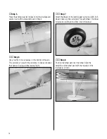
Page 17: ...ing gear fairing from the bottom of the fuselage Step 3 Attach the landing gear to the fuselage using four 8 32 x 11 4 inch socket head screws four 8 washers and four 8 lock washers Note The landing gear attachment is designed so that the hardwood runners are tapped for the 8 32 bolts and no nuts are needed This is an excellent design feature used on all Carden Aircraft models that allows the thre...

Page 18: ...des an area for the setscrews to bite and reduces the chance of losing a wheel during flight Step 7 Attach the wheels to the landing gear using two 5 32 inch wheel collars and two setscrews for each wheel The wheel collars are positioned on either side of the wheel Step 8 Position the wheel pant over the wheel Align the centerline of the wheel pant with the top edge of the fuselage as shown ...

Page 19: ...rill bit to drill the two holes to install the 4 40 blind nuts inside the wheel pant Step 11 Install two 4 40 blind nuts inside the wheel pant Step 12 Secure the wheel pant to the landing gear using two 4 40 x 1 2 inch socket head screws and two 4 washers Important Make sure to use threadlock on the screws to prevent them from vibrating loose ...

Page 20: ...1 4 inch split washer 4 Throttle pushrod Required Tools and Adhesives Medium CA Drill Drill bit 1 4 inch 6mm Ruler Square Hobby knife Razor saw Rotary tool Note The DA 50 can be used with either the MTW 75 canister and header exhaust system or with the Slimline Pitts muffler both available from Desert Aircraft This section shows installation of the DA 50 using the MTW canister muffler system Step ...

Page 21: ... center as done on each side of the firewall and drill a 1 4 inch hole at each of these marks Also drill a hole through the block to be positioned at the top for the throttle linkage if needed Step 4 Attach the engine to the firewall using four 1 4 20 bolts and four 1 4 inch split washers from the inside of the firewall Position the engine mounting blocks behind the engine with the thin side posit...

Page 22: ...tos showing the in cowl muffler show the other version Either are fine Route the fuel line and throttle linkage accordingly Step 7 Install the supplied canister mount into the area in front of the fuel tank Assemble the canister and header using the coupler and clamps provided with the muffler The header may need to be cut shorter so the exhaust from the canister is positioned in front of the forw...

Page 23: ... the aircraft Bolt the exhaust header to the engine Step 9 Screw the canister mount in place with four wood screws Step 10 Cut out the cowling as shown to clear the exhaust and spark plug cap Step 11 If using a Pitts style muffler mount the muffler to the engine at this time ...

Page 24: ...harden plywood cowl ring to avoid drawing in the cowl and chafing the fuselage covering when tightening this screw A small gap should exist between the cowl and the face of the fuselage Should the gap decrease to a point where the cowl begins to rub then add a small washer to act as a spacer Step 13 Install the ignition and ignition battery onto the engine box as shown Mounting the ignition to the...

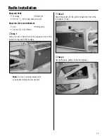
Page 25: ...ch 13mm Step 1 Drill a 1 2 inch 13mm hole in the fuselage to mount the fuel dot to the side of the fuselage Note Be sure to provide clearance for wing before drilling the fuel dot hole Step 2 Mount the switch for the ignition toward the front of the fuselage as shown Step 3 Secure the radio battery inside the fuselage Radio Installation ...

Page 26: ...6 inch 9 inch 12 inch 24 inch and 36 inch leads are available and in sophisticated aircraft we ve found it best to mount the remote receivers in different parts of the aircraft keeping the remote antennas as far away as practical from any conductive materials A typical installation would include the main receiver mounted in the conventional location in the fuselage and the remote antennas in the n...

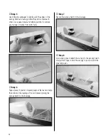
Page 27: ...nstrument panels from the decal sheet Note there is a front and rear instrument panel decal Step 2 Remove the backing and secure the instrument panels into position in the canopy hatch Step 3 Remove a section of the covering from the canopy hatch from under where the pilot will sit Use 30 minute epoxy to secure the pilot in the cockpit Step 4 Once the epoxy has fully cured check that the screws ho...

Page 28: ...ny residue or debris from both items Step 6 Tape a piece of plastic or waxed paper at the rear and align the bottom of the fuselage This will prevent gluing the canopy hatch to the fuselage Step 7 Secure the canopy hatch to the fuselage Step 8 Use canopy glue to attach the canopy to the canopy hatch Use painter s tape to hold the canopy in position until the glue fully cures ...

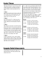
Page 29: ...a few points as necessary to fine tune the throws to match up left and right sides and up and down throws so all is symmetrical This is necessary to ensure that the mechanical advantage is as great as possible When setting up the Yak or any model for 3D aerobatics mechanical advantage is lower in order to get the large control surface deflections needed This will cause faster servo wear Using an i...

Page 30: ...d pen With a helper lift the aircraft with your index finger at the location marked on the wing If the nose of your aircraft hangs low add weight to the rear of the aircraft If the tail hangs low add weight to the nose of the aircraft Stick on weights are available at your local hobby store and work well for this purpose The center of gravity can also be measured at the wing tip by measureing forw...

Page 31: ...n doing 3D aerobatics flip to 3D rates just before the maneuver As soon as the maneuver is done flip back down to low rate to avoid over controlling the model A 7 channel or greater computer radio is highly recommended This allows the following features Mixing the right aileron to the left aileron flaperon mix Electronically adjustable aileron differential Mixing the right elevator to the left ele...

Page 32: ...r control linkage setups and flying techniques large models are not Don t let that scare you away from large models they are truly one of the best flying experiences in RC that money can buy However please pay particular attention to the following areas Never attempt to make full throttle dives Large models perform much more like full size aircraft than small models If the airframe goes too fast s...

Page 33: ...llection and recycling of your waste equipment at the time of disposal will help to conserve natural resources and ensure that it is recycled in a manner that protects human health and the environment For more information about where you can drop off your waste equipment for recycling please contact your local city office your household waste disposal service or where you purchased the product 33 ...

Page 34: ...with metal blade propellers or with gaseous boosts other than air nor will I operate model aircraft with fuels containing tetranitromethane or hydrazine 8 I will not operate model aircraft carrying pyrotechnic devices which explode burn or propel a projectile of any kind Exceptions include Free Flight fuses or devices that burn producing smoke and are securely attached to the model aircraft during...

Page 35: ... site a day use agreement between sites or testing which determines that no interference exists A frequency management agreement may exist between two or more AMA chartered clubs AMA clubs and individual AMA members or individual AMA members Frequency management agreements including an interference test report if the agreement indicates no interference exists will be signed by all parties and copi...

Page 36: ... 2008 Horizon Hobby Inc 4105 Fieldstone Road Champaign Illinois 61822 877 504 0233 horizonhobby com 12654 ...

Reviews: