background image

-20-

PREPARING FOR OPERATION


Hydraulics

The 

Top Shot

 requires a 6-hose hook-up: 

- 2 hoses for raising/lowering the main auger.

- 2 hoses for opening/closing the discharge door.

- 2 hoses for operating the discharge deflector. 

Optional:

- 2 hoses for the optional lid.

Before starting the tractor, make sure each set 

of hydraulic hoses connects to the appropriate 

set of remote outlets on the tractor. Operate the 

tractor valve to fill the hydraulic lines and operate 

the  cylinders. Add  hydraulic  fluid  to  the  tractor 

system, as required. 

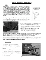
Attach the 

Top Shot

 PTO to the tractor PTO shaft locking 

it into position and check distance by the following:
1.  Maintain a straight alignment between the


Top Shot


and the tractor.

 2. Maintain a distance of 6″- 12″ between the top of  

     the tractor drawbar and the center of the   


     tractor PTO. An 8″ distance is standard.

After the correct distance is obtained, slide back the coupler lock and attach the PTO drive to the tractor 

PTO shaft. Make sure that the coupler locks onto the PTO shaft; slide it back and forth until it locks. 

NOTE:


Do 

NOT

 attempt to use a hammer to help in attaching the PTO drive connection.

NOTE:


Remove the tractor 3-point quick hitch if the tractor is equipped with one. Tractor 3-point arms 

must be removed or positioned so they do not come in contact with the 

Top  Shot

 tongue or PTO. 


Failure to heed will cause damage and void the warranty.


PTO

The 

Top Shot

 is equipped with a constant velocity telescoping PTO drive 

shaft. This constant velocity capability results in a smooth, quiet running 

drive line without power fluctuation. The 

Top Shot

 can only be properly 

hooked-up to a tractor which has PTO and hitch dimensions conforming 

to ASAE Standard S203. Horsepower required may vary according to the 

consistency of material to be spread, ground speed, and terrain. To prevent 

damage to the telescoping PTO drive, DO NOT allow the tractor’s rear tires 

to make contact with the PTO or 

Top Shot

 while making sharp turns. Be 

careful when pulling the 

Top Shot

 with a tractor that is equipped with dual 

rear tires.

NOTE:


The maximum joint angle must not exceed 80º whether in operation 

or not. Any angle greater than 80º, will result in damage to the joint. For 

continuous operation, the maximum joint angle must be limited to 35º. Any 

continuous operation at angles greater than 35º will shorten joint life.

Summary of Contents for 5234

Page 1: ...ND UNDERSTAND THIS MANUAL BEFORE READ AND UNDERSTAND THIS MANUAL BEFORE OPERATING THIS EQUIPMENT UNSAFE OPERATION OPERATING THIS EQUIPMENT UNSAFE OPERATION OR MAINTENANCE OF THIS EQUIPMENT CAN RESULT...

Page 2: ...Safety Signs 10 Safety Decals 11 12 Safety Information Warning Owner Must Read and Understand 13 Cap Screw Torque Values 14 Hydraulic Torque Specs 15 16 Set Up Assembly 17 Transporting 18 Storage 18 P...

Page 3: ...ded solely to the original purchaser of the product is terminated upon any subsequent transfer or sale from or by the original purchaser and extends no third party benefits or rights whatsoever The wa...

Page 4: ...NT Congratulations on your selection of an H S product Your new H S product has been manufactured of the finest quality materials and components The performance you receive from your machine is largel...

Page 5: ..._________________________________ Serial Number __________________________________________________ You have received the Operator s Manual for this product Yes _____ No _____ Interested in receiving t...

Page 6: ...4 Intentionally Left Blank...

Page 7: ...ttached and there are no visible leaks Guards and shields are secure Wheels are properly mounted Tires are inflated to correct pressure Chain tension is properly adjusted See Adjustment Chapter of thi...

Page 8: ...6 Intentionally Left Blank...

Page 9: ...ed for proper operation and long life of machine Show customer the Lubrication Chapter of the Operator s Manual Give the customer the Operator s Manual and make sure they read and understand all opera...

Page 10: ...8 Intentionally Left Blank...

Page 11: ...EVER YOUR PERSONAL SAFETY IS INVOLVED TAKE TIME TO BE CAREFUL REMEMBER THE CAREFUL OPERATOR IS THE BEST OPERATOR MOST ACCIDENTS ARE CAUSED BY HUMAN ERROR CERTAIN PRECAUTIONS MUST BE OBSERVED TO PREVEN...

Page 12: ...FORMATION OBSERVE MAXIMUM TRANSPORT SPEED The maximum transport speed for this implement is 32 km h 20 mph Some tractors are capable of operating at speeds that exceed the maximum transport speed of t...

Page 13: ...11 SAFETY INFORMATION...

Page 14: ...12 SAFETY INFORMATION...

Page 15: ...r engine remove ignition key and allow all mechanisms to stop Before cleaning or working on the Top Shot detach the PTO shaft and completely disengage the tractor hydraulics DO NOT attempt to perform...

Page 16: ...Dry Ft Lbs Lube Ft Lbs Inch Lbs Inch Lbs Inch Lbs Inch Lbs 1 4 20 1 4 28 5 5 6 3 4 2 4 7 8 10 6 3 7 2 12 14 9 10 75 2 94 0 78 8 99 0 61 5 77 0 68 6 87 0 5 16 20 5 16 28 11 12 8 9 17 19 13 14 24 27 18...

Page 17: ...15 HYDRAULIC FITTING TORQUE SPECIFICATIONS...

Page 18: ...16 HYDRAULIC FITTING TORQUE SPECIFICATIONS...

Page 19: ...bly and adjustment and make sure that all bolts are tightened 4 Securely retighten after a few hours of operation as bolts can loosen up on new machinery 5 Lubricate the Top Shot completely SET UP ASS...

Page 20: ...G ON HIGHWAY To view beyond the back of the larger trailer mounted Top Shot when transporting the unit on a public highway consider obtaining and installing a rearview mirror on your tractor with a wi...

Page 21: ...tion on the left side of the Spreader If the Top Shot is attached to a tractor with a clevis hitch hammer strap style drawbar the hammer strap must be removed to prevent damage to the IID guarding and...

Page 22: ...o use a hammer to help in attaching the PTO drive connection NOTE Remove the tractor 3 point quick hitch if the tractor is equipped with one Tractor 3 point arms must be removed or positioned so they...

Page 23: ...auger and drive line foreign objects such as stones timber or metal should never be placed into the Top Shot tank 1 In winter or freezing temperatures make sure the auger and expeller are free to rot...

Page 24: ...hot with the auger fully raised the discharge gate fully raised and blocked Position the jack height so that liquids will run forward to the discharge opening 3 Before loading the Top Shot again unblo...

Page 25: ...When spreading material which is susceptible to bridging the auger should be cycled up and down frequently to provide a more consistent feeding of material into the expeller NOTE Do NOT exceed the 10...

Page 26: ...the auger the expeller or both ADJUSTABLE EXPELLER SHIELD The Top Shot features a hydraulic adjust expeller deflector shield to direct material and provide the best possible performance for delivery...

Page 27: ...ing discharged In freezing temperatures leave the discharge gate partially opened when the unit is parked overnight to prevent the gate from freezing against the bottom of the opening A discharge gate...

Page 28: ...against the spring tension and slide the yoke onto tractor PTO shaft Release the locking collar and move the yoke ahead or back until the lock engages into the groove on the shaft NOTE When the sprea...

Page 29: ...proper tension replace the worn chain Shield open for viewing Shield open for viewing Auger Drive Chain Idlers The jackshaft and auger drive chain tighteners are spring loaded Use the eye bolt adjustm...

Page 30: ...gainst the tank then retighten the retaining hardware Grease the slide assembly to ensure a leak free seal DISCHARGE GATE The discharge gate is retained by adjustable angles that secure the gate to th...

Page 31: ...hanges some chain length modifications may be required depending on the condition of the chain and size of the sprocket installed IMPORTANT When resuming operation place the tractor throttle at idle b...

Page 32: ...drag is felt when wheel is turned Back nut off and insert cotter pin into first hole that you see as you back the nut off bend cotter pin over and reinstall cap WHEEL HUB OIL BATH OIL ASSEMBLY DO NOT...

Page 33: ...3 modes Net Tare and Gross Model Digi Star NT460 An optional factory installed Digi Star NT460 scale system is available for accurate weight measurement and displaying actual tons per acre The Indicat...

Page 34: ...e drive line GEAR BOX To check the oil level on the gear box remove the CHECK LEVEL PLUG on the back side of the gear box to see if the oil level is at the bottom of the hole If oil is needed to bring...

Page 35: ...ing the chains aligned with sprockets will also lengthen the life of the sprockets and drive chains The discharge gate control cylinder shaft discharge door deflector shield cylinder shaft and both fr...

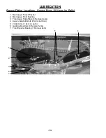
Page 36: ...Main Auger Thrust Washer 2 Main Auger Front Bearing 3 Front Auger Slide Plate 4 Remote Zerks 4 Auger Jackshaft Zerk in Sprocket Hole 5 2 Idler Arms 1 Zerk on each 6 Gearbox Bearings 4 Remote Zerks 7 F...

Page 37: ...ar Auger Bearing WHEEL BEARING LUBRICATION GREASEABLE HUBS Grease wheel bearings on the hub zerk as needed depending on amount of travel FOLLOW THE INSTRUCTIONS ABOVE FOR GREASEABLE HUBS AND BELOW FOR...

Page 38: ...No step stay clear 9194B 1 Never Allow Riders on this Machine 11210A 1 Discharge gate opening decal 11210B 1 Do not remove shields 11599 5 Do not go near leaks 32320 1 Spiral Decal for Main Auger Shaf...

Page 39: ...37 DECAL LOCATION DCAMB 111209C 71064 71071 111209C 71188B 71071 093366 093020 022310 DCAMB 71064 093020 022310 71064 DCAMB 111209B 11210B 093020 DCRED 86060...

Page 40: ...AL LOCATION 9194B 54033 51010 111209C LW112901 111209A 71092 1494B 66076 9194A 5896B 82602 1494L 8515 311 82602 5896B 9194A 111209A 093020 9194A 9194A 11599 1494B 72203A 1494J 102196 DCAMB 71094 84044...

Page 41: ...9 DECAL LOCATION 1494A 11599 Remote Grease 093020 1494A 11599 111209A 11211176 081312 51010 111209B 111210 DCAMB 11599 51010 111209B 86060 DCAMB 093020 51010 111209C 11599 TFM97 DCRED DCRED 32320 7108...

Page 42: ...n tension See details in Adjustments Chapter Replace sprocket or chain 3 Excessive chain and or sprocket wear Sprockets are NOT properly aligned Inadequate chain tension Re align sprockets See item 6...

Page 43: ...41 SERVICE NOTES...

Page 44: ...42 SERVICE NOTES...

Page 45: ......

Page 46: ...Manufactured By H S MANUFACTURING CO INC 2608 S HUME AVE MARSHFIELD WI 54449 715 387 3414 hsmfgco com H S MFG CO products approved for the FEMA SEAL OF QUALITY...

Reviews: