Installation
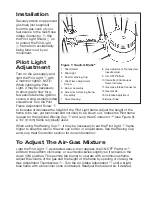
Securely attach an approved
gas hose (not supplied)
from the gas cock of your
fuel source to the Gas Hose
Intake Connector
-
. Slip
the Pilot Light Shield
1
on
to protect the Pilot Light
2
flame from accidentally
being blown out by air
movement.
Pilot Light
adjustment
Turn on the gas supply and
light the Pilot Light
2
with
a match or lighter. NOTe:
When lighting the Pilot
Light, it may be necessary
to allow gas to flow for a
few seconds before ignition
occurs. Using a small slotted
screwdriver, turn the Pilot
Flame Adjustment Screw
4
to increase or decrease the height of the Pilot Light flame. Adjust the height of the
flame to be low, yet functional and not likely to be blown out. Unless the Pilot flame
is used for the optional Waxing Cup
t
and Loop Heat Conductor
y
(see Figure 3),
a 1/4” (6 mm) flame is typically used.
When using the Waxing Cup
t
, it may be necessary to set the Pilot Light
2
flame
higher to keep the wax in the wax cup soft or in a liquid state. See the Waxing Cup
and Loop Heat Conductor section for more information.
To adjust The air-Gas Mixture
Light the Pilot Light
2
as directed above, then depress the ON-OFF Platform
9
and turn the platform clockwise, or counterclockwise, slightly so it remains in the
down (ON) position. This permits the burner to operate with a continuous flame.
Adjust the volume of the gas and the height of the flame by opening or closing the
Gas Adjustment Thumbscrew
8
. Turn the Air-Intake Adjustment
q
until a bright
blue flame with a blue inner cone is obtained. Readjust the fuel and air, if desired.
1 r
q =
- 0
9
8
2
4 3
5 6
7
Figure 1: Touch-O-Matic
®
1 Pilot Shield
2 Pilot Light
3 Post for Waxing Cup
4 Pilot Flame Adjustment
Screw
5 Burner Assembly
6 Screw for Detaching Burner
Assembly
7 Valve Housing
8 Gas Adjustment Thumbscrew
(needle valve)
9 ON-OFF Platform
10 Intermittent/Continuous
Flame Indicator
11 Gas Hose Intake Connector
12 Gas Nozzle
13 Air-Intake Adjustment
16 Burner Tube


